 |
ac6wzw00000012
id01121a951500
D-code
Open Capsule Cover
1.Open in the order indicated in the table.
ac6wzw00000012
|
| Step |
Part name |
|---|---|
|
1
|
Rotating fastener
|
|
2
|
Capsule cover
|
|
3
|
Clip
|
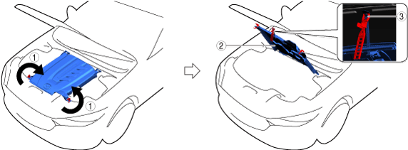
Opening capsule cover note
1.Open the capsule cover as shown in the figure.
ac6wzw00000013
|
| Symbol |
Content |
|---|---|
 |
Servicing procedure
|
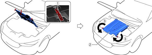
Closing capsule cover note
1.Close the capsule cover as shown in the figure.
ac6wzw00000014
|
| Symbol |
Content |
|---|---|
| |
Servicing procedure
|
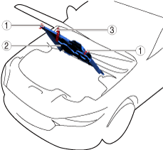
Remove Front Under Cover No.2
1.Remove using the procedure shown in the figure.
azzdjw00000583
|
| Step |
Part name |
 |
|---|---|---|
|
1
|
Bolt
|
11 N·m {110 kgf·cm, 95 in·lbf}
|
|
2
|
Fastener
|
—
|
|
3
|
Front under cover No.2
|
—
|
Remove Front Under Cover No.1
1.Remove using the procedure shown in the figure.
azzdjw00000582
|
| Step |
Part name |
|
|---|---|---|
|
1
|
Bolt
|
11 N·m {110 kgf·cm, 95 in·lbf}
|
|
2
|
Screw
|
2 N·m {20 kgf·cm, 17 in·lbf}
|
|
3
|
Fastener
|
—
|
|
4
|
Front under cover No.1
|
—
|
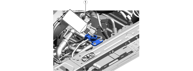
Drain Engine Coolant (Main)
1.Open the coolant reserve tank cap.
azzdjw00007646
|
|
1
|
Coolant reserve tank cap
|
2.Drain the engine coolant (main) from the coolant reserve tank.
3.Remove the drain plug (main) and drain the engine coolant (main).
azzdjw00005248
|
|
1
|
Drain plug (main)
|
4.Install the drain plug (main).
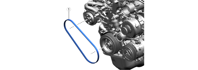
Remove Water Pump Drive Belt
1.Remove in the order indicated in the table.
azzdjw00004394
|
| Step |
Part name |
|---|---|
|
1
|
Water Pump Drive Belt
|
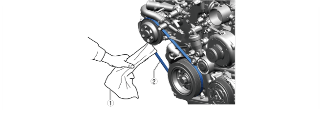
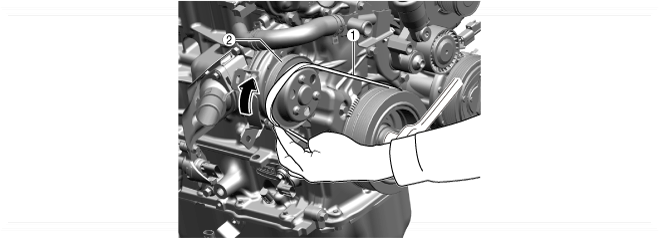
Water pump drive belt removal note
1.Apply a cloth to the water pump drive belt as shown in the figure.
azzdjw00004395
|
|
1
|
Rag
|
|
2
|
Water Pump Drive Belt
|
2.Pull the cloth in the direction of the arrow and rotate the crankshaft pulley clockwise.
azzdjw00004396
|
|
1
|
Rag
|
|
2
|
Crankshaft pulley
|
3.Remove the water pump drive belt.
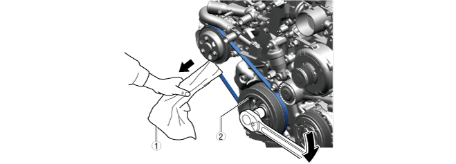
Water pump drive belt installation note
1.Set one side of the water pump drive belt in the groove of the crankshaft pulley.
2.Set the other side of the water pump drive belt in the step of the water pump pulley.
azzdjw00004397
|
|
1
|
Water Pump Drive Belt
|
|
2
|
Water pump pulley
|
3.Pushing up the belt so that it is fitted in from the step of the water pump pulley to the groove of the pulley, rotate the crankshaft pulley clockwise.
azzdjw00004398
|
|
1
|
Water Pump Drive Belt
|
|
2
|
Water pump pulley
|
4.After the belt is installed, rotate the crankshaft pulley clockwise approx. 180° and verify that the water pump drive belt is installed correctly.
Water pump pulley remove
1.Remove in the order indicated in the table.
azzdjw00005099
|
| Step |
Part name |
 |
|---|---|---|
|
1
|
Bolt
|
9.5 N·m {97 kgf·cm, 84 in·lbf}
|
|
2
|
Water pump pulley
|
—
|
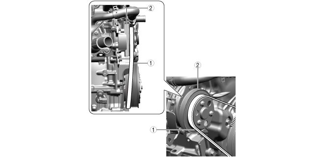
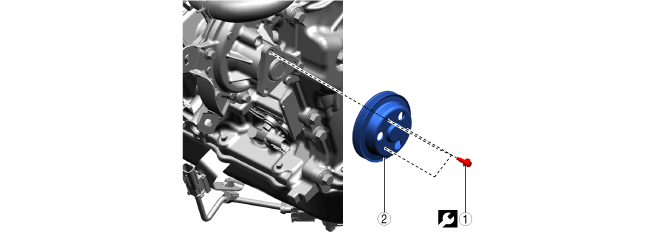
Water Pump Component Removal Note
1.Align the holes of the water pump pulley with those of the water pump as shown in the figure.
azzdjw00005101
|
| Symbol |
Content |
|---|---|
|
1
|
Hole
|
|
2
|
Water pump pulley
|
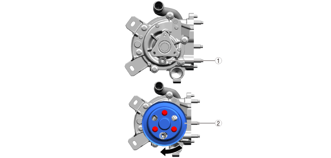
2.Insert an appropriate bolt (approximately 70 mm {2.8 in} in length) into the hole of the water pump as shown in the figure to lock the rotation of the water pump pulley.
azzdjw00005102
|
| Symbol |
Content |
|---|---|
|
1
|
Water pump pulley
|
|
2
|
Bolt
|
3.Remove the bolt used for rotation stop.
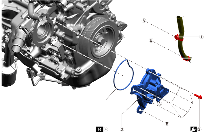
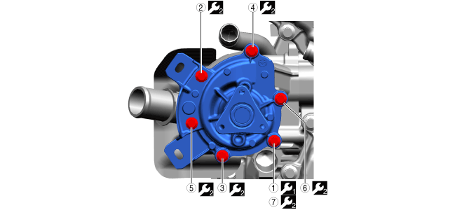
Remove Water Pump
1.Remove in the order indicated in the table.
azzezw00000898
|
| Step |
Part name |
 |
 |
|---|---|---|---|
|
1
|
Wiring harness clip
|
—
|
—
|
|
2
|
Screw
(See
Screw installation note)
|
—
|
9.5 N·m {97 kgf·cm, 84 in·lbf}
|
|
3
|
Water pump
|
—
|
—
|
|
4
|
Gasket
|
Replacement part
|
—
|
Screw installation note
1.Install the screws using the procedure shown in the figure.
azzdjw00005406
|
| Symbol |
Content |
|---|---|
| |
Servicing procedure
|
 |
Temporarily tighten
|
 |
9.5 N·m {97 kgf·cm, 84 in·lbf}
|
Install in Reverse Order of Removal
1.Install in the reverse order of removal.
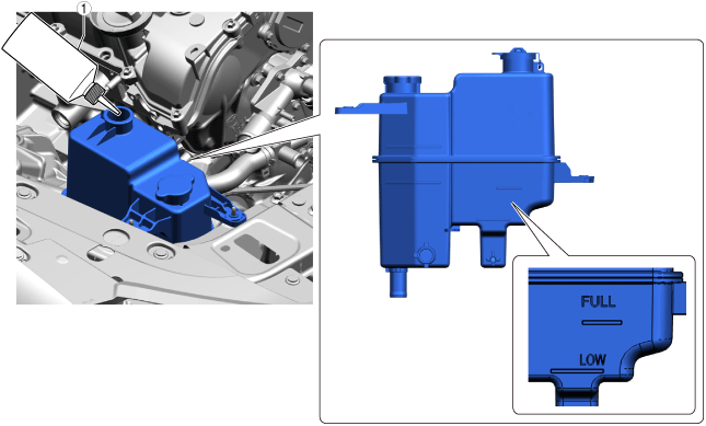
Add Engine Coolant (Main)
1.Add engine coolant (main) to the top surface of the radiator filler port.
azzdjw00007645
|
|
1
|
Bottle
|
2.Add engine coolant (main) to the coolant reserve tank up to the FULL line.
azzdjw00007652
|
|
1
|
Bottle
|
Total coolant amount (reference)
| Specification |
Capacity |
|---|---|
|
With e-SKYACTIV PHEV
|
8.6 L {9.1 US qt, 7.6 Imp qt}
|
|
Without e-SKYACTIV PHEV
|
7.0 L {7.4 US qt, 6.2 Imp qt}
|
3.After the engine coolant (main) is added up to the FULL line of the coolant reserve tank, add an additional 0.26 L {0.27 US qt, 0.23 Imp qt.}.
Perform Engine Coolant (Main) Air Bleeding (With e-SKYACTIV PHEV)
1.Perform the following procedure switch to compulsory engine start mode.
2.Perform the engine coolant (main) air bleeding using the following procedure.
3.Stop the engine and wait until the engine coolant (main) temperature decreases.
4.If the engine coolant (main) level is low, add engine coolant (main) and inspect the coolant amount.
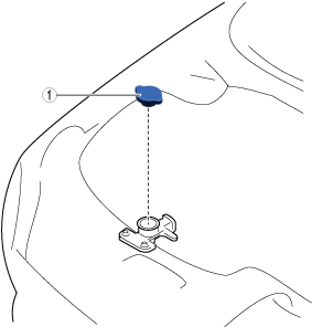
Remove Cooling System Cap
1.Remove in the order indicated in the table.
ac6wzw00000094
|
| Step |
Part name |
|---|---|
|
1
|
Cooling system cap
|
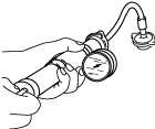
Inspect For Engine Coolant Leakage
1.Install the radiator cap tester to the filling port.
ampjjw00003132
|
2.Apply pressure using the radiator cap tester.
3.When pressurizing the radiator, verify that the pressure is maintained.
Install cooling system cap
1.Install in the order indicated in the table.
ac6wzw00000094
|
| Step |
Part name |
|---|---|
|
1
|
Cooling system cap
|