 |
ac6wzw00000012
id01121a951400
D-code
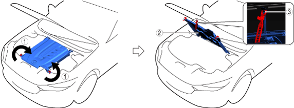
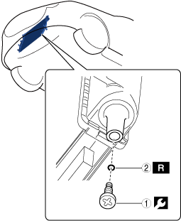
Open Capsule Cover
1.Open in the order indicated in the table.
ac6wzw00000012
|
| Step |
Part name |
|---|---|
|
1
|
Rotating fastener
|
|
2
|
Capsule cover
|
|
3
|
Clip
|
Opening capsule cover note
1.Open the capsule cover as shown in the figure.
ac6wzw00000013
|
| Symbol |
Content |
|---|---|
 |
Servicing procedure
|
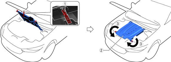
Closing capsule cover note
1.Close the capsule cover as shown in the figure.
ac6wzw00000014
|
| Symbol |
Content |
|---|---|
| |
Servicing procedure
|
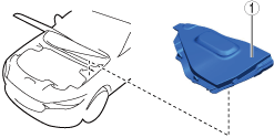
Remove Cover Assembly (Passenger's Side)
1.Remove using the procedure shown in the figure.
azzdjw00001856
|
| Step |
Part name |
|---|---|
|
1
|
Cover assembly
(See
Cover assembly removal note.)
|
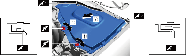
Cover assembly removal note
1.Remove the cover assembly as shown in the figure.
azzdjw00001857
|
| Symbol |
Content |
|---|---|
| |
Servicing procedure
|
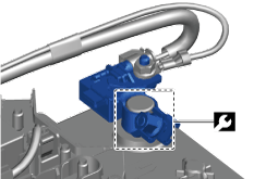
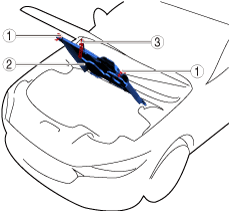
Disconnect Negative Lead-Acid Battery Terminal
With e-SKYACTIV PHEV
1.Verify that the charge cable is not connected to the charging port.
2.Keep the driver's door open.
3.Keep the hood open.
4.Keep the main power switched ON (READY on) for 3 s or more.
5.Switch the main power OFF and start measuring the time since the main power was switched OFF using a stopwatch.
6.Switch the main power OFF and wait for 5 min.
7.Disconnect the negative lead-acid battery terminal within 25 min from switching the main power OFF in Step 5 using the following procedure.
azzezw00000929
|
| Symbol |
Content |
|---|---|
 |
5 N·m {51 kgf·cm, 44 in·lbf}
|
Without e-SKYACTIV PHEV
1.Connect the M-MDS to the DLC-2.
2.Turn ON the engine switch (engine stop).
3.Verify the[BATT_SOC] value using the M-MDS data logger function.
4.Record the [BATT_SOC] value.
5.Turn OFF the engine switch.
6.Disconnect the current sensor connector.
7.Disconnect the negative battery terminal.
azzezw00000929
|
| Symbol |
Content |
|---|---|
| |
5 N·m {51 kgf·cm, 44 in·lbf}
|
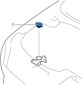
Remove Cooling System Cap (Sub) (PYUL)
1.Remove in the order indicated in the table.
azzdjw00005276
|
| Step |
Part name |
|---|---|
|
1
|
Cooling system cap (sub)
|
Remove Cooling System Cap
1.Remove in the order indicated in the table.
ac6wzw00000094
|
| Step |
Part name |
|---|---|
|
1
|
Cooling system cap
|
Drain Engine Coolant (Main)
1.Open the coolant reserve tank cap.
azzdjw00007646
|
|
1
|
Coolant reserve tank cap
|
2.Drain the engine coolant (main) from the coolant reserve tank.
3.Remove the drain plug (main) and drain the engine coolant (main).
azzdjw00005248
|
|
1
|
Drain plug (main)
|
4.Install the drain plug (main).
Drain EV System Coolant
acxuuw00002056
|
EV system coolant capacity (approx. quantity)
| Capacity |
|---|
|
9.6 L {10 US qt, 8.4 Imp qt}
|
1.Remove the cooling system cap.
ac6wzw00000094
|
|
1
|
Cooling system cap
|
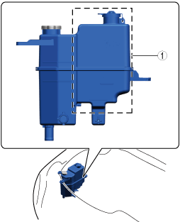
2.Drain the EV system coolant from the coolant reserve tank (sub).
ac6wzw00000095
|
|
1
|
Coolant reserve tank (sub)
|
3.Remove the drain plug (sub).
azzezw00000341
|
| Symbol |
Content |
|---|---|
| |
Servicing procedure
|
 |
1 N·m {11 kgf·cm, 9 in·lbf}
|
 |
Drain cock gasket
|
4.Draining the EV system coolant.
5.Install the radiator drain plug (sub).
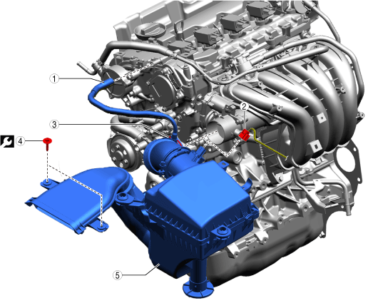
Remove Air Cleaner Component
1.Remove in the order indicated in the table.
azzezw00000899
|
| Step |
Part name |
|
|---|---|---|
|
1
|
Ventilation hose
|
—
|
|
2
|
Connector
|
—
|
|
3
|
Hose clamp
|
3 N·m {30 kgf·cm, 26 in·lbf}
|
|
4
|
Bolt
|
9.5 N·m {95 kgf·cm, 82 in·lbf}
|
|
5
|
Air cleaner component
|
—
|
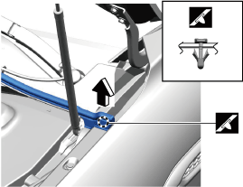
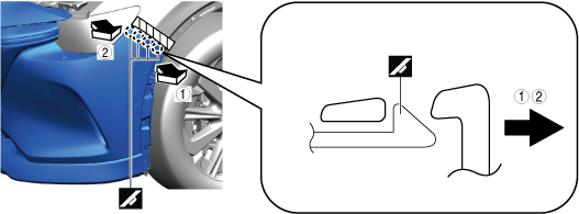
Remove Passenger Side Edge Rubber
1.Remove using the procedure shown in the figure.
azzdjw00000676
|
| Step |
Part name |
|---|---|
|
1
|
Fastener
|
|
2
|
Edge rubber
(See
Edge rubber removal note.)
|
Edge rubber removal note
1.Partially peel back the cowl grille weatherstrip until the A-pillar trim can be removed.
azzdjw00000677
|
2.Remove the edge rubber.
Remove Driver Side Edge Rubber
1.Remove using the procedure shown in the figure.
azzdjw00000674
|
| Step |
Part name |
|---|---|
|
1
|
Fastener
|
|
2
|
Edge rubber
(See
Edge rubber removal note.)
|
Edge rubber removal note
1.Partially peel back the cowl grille weatherstrip until the A-pillar trim can be removed.
azzdjw00000675
|
2.Remove the edge rubber.
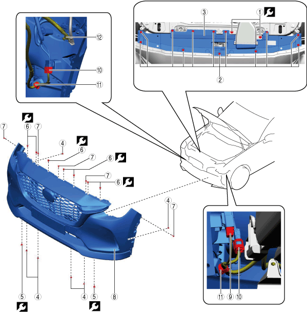
Remove Front Bumper
1.Remove using the procedure shown in the figure.
azzdjw00000884
|
| Step |
Part name |
Applicable condition |
|
|---|---|---|---|
|
1
|
Bolt
|
—
|
9.5 N·m {95 kgf·cm, 82 in·lbf}
|
|
2
|
Fastener
|
—
|
—
|
|
3
|
Latch Cover
|
—
|
—
|
|
4
|
Fastener
|
—
|
—
|
|
5
|
Bolt
|
—
|
8.5 N·m {85 kgf·cm, 74 in·lbf}
|
|
6
|
Bolt
|
—
|
8.5 N·m {85 kgf·cm, 74 in·lbf}
|
|
7
|
Fastener
|
—
|
—
|
|
8
|
Front bumper
(See
Front bumper removal note.)
|
—
|
—
|
|
9
|
Connector
|
With 360° view monitor
|
—
|
|
10
|
Connector
|
—
|
—
|
|
11
|
Wiring harness clip
|
—
|
—
|
|
12
|
Headlight washer hose
|
With headlight washer
|
—
|
Front bumper removal note
1.Remove the front bumper as shown in the figure.
azzdjw00000885
|
| Symbol |
Content |
|---|---|
 |
Protective tape attachment positions
|
| |
Servicing procedure
|
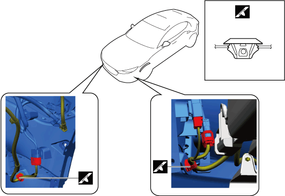
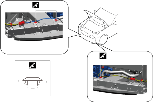
Wiring harness clip removal note
1.Remove the wiring harness clips as shown in the figure.
azzdjw00000887
|
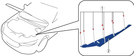
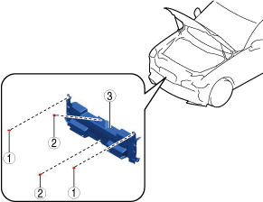
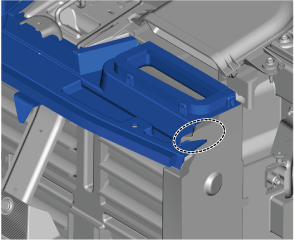
Remove Center Seal Plate
1.Remove using the procedure shown in the figure.
azzdjw00003455
|
| Step |
Part name |
|---|---|
|
1
|
Fasteners
|
|
2
|
Fasteners
|
|
3
|
Center seal plate
|
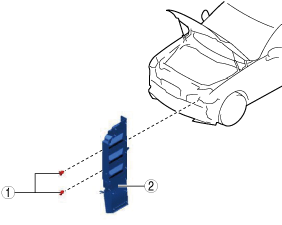
Remove Bracket
azzdjw00001681
|
1.Remove using the procedure shown in the figure.
azzdjw00003780
|
| Step |
Part name |
|
|---|---|---|
|
1
|
Bolt
|
11 N·m {110 kgf·cm, 95 in·lbf}
|
|
2
|
Fasteners
|
—
|
|
3
|
Bracket
(See
Bracket installation note.)
|
—
|
Bracket installation note
1.After installing the front bumper, refer to [HOOD ADJUSTMENT] and measure the space between the hood and the front bumper.
2.If the measured value is not within the standard, move the front bumper bracket and adjust the installation position.
Remove Intake Air Guide (Upper)
1.Remove using the procedure shown in the figure.
azzdjw00003781
|
| Step |
Part name |
|---|---|
|
1
|
Intake air guide (upper)
|
Intake air guide (upper) removal note
1.Remove the intake air guide (upper) as shown in the figure.
azzdjw00001683
|
2.Verify that the intake air guide (upper) is inserted into the seal plate and engaged.
azzdjw00007519
|
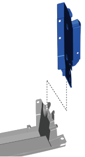
Remove Passenger's Side Seal Plate
1.Remove using the procedure shown in the figure.
azzdjw00003783
|
| Step |
Part name |
|---|---|
|
1
|
Fasteners
|
|
2
|
Seal plate
|
Passenger's Side seal plate installation note
1.Verify that the passenger's side seal plate is inserted into the intake air guide (lower) groove and engaged.
azzdjw00007520
|
Remove Driver's Side Seal Plate
1.Remove using the procedure shown in the figure.
azzdjw00003782
|
| Step |
Part name |
|---|---|
|
1
|
Fasteners
|
|
2
|
Seal plate
|
Driver's side seal plate installation note
1.Verify that the driver's side seal plate is inserted into the intake air guide (lower) groove and engaged.
azzdjw00007520
|
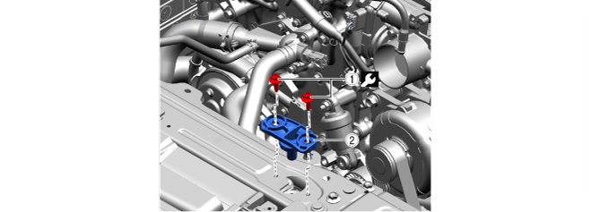
Remove Radiator Mount (LH)
1.Remove in the order indicated in the table.
azzdjw00005754
|
| Step |
Part name |
 |
|---|---|---|
|
1
|
Bolt
|
9.5 N·m {95 kgf·cm, 82 in·lbf}
|
|
2
|
Radiator mount (LH)
|
—
|
Remove Radiator Mount (RH)
1.Remove in the order indicated in the table.
azzdjw00006812
|
| Step |
Part name |
 |
|---|---|---|
|
1
|
Bolt
|
9.5 N·m {95 kgf·cm, 82 in·lbf}
|
|
2
|
Radiator mount (RH)
|
—
|
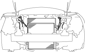
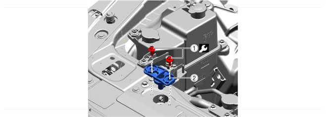
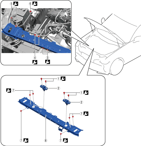
Remove Shroud Upper Member
1.Remove using the procedure shown in the figure.
azzdjw00001829
|
| Step |
Part name |
|
|---|---|---|
|
1
|
Bolt
|
9.5 N·m {95 kgf·cm, 82 in·lbf}
|
|
2
|
Radiator mount bracket
|
—
|
|
3
|
Bolt
|
11.5 N·m {117 kgf·cm, 102 in·lbf}
|
|
4
|
Bolt
|
9.5 N·m {95 kgf·cm, 82 in·lbf}
|
|
5
|
Nut
|
9.5 N·m {95 kgf·cm, 82 in·lbf}
|
|
6
|
Bolt
|
9.5 N·m {95 kgf·cm, 82 in·lbf}
|
|
7
|
Bolt
|
26 N·m {2.65 kgf·m, 19.2 ft·lbf}
|
|
8
|
Shroud upper member
|
—
|
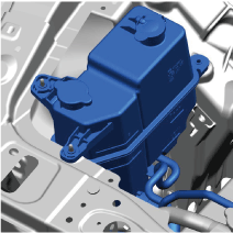
Shroud upper member removal note
1.Move the coolant reserve tank aside until the shroud upper member can be removed.
azzdjw00001830
|
2.Remove the shroud upper member.
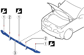
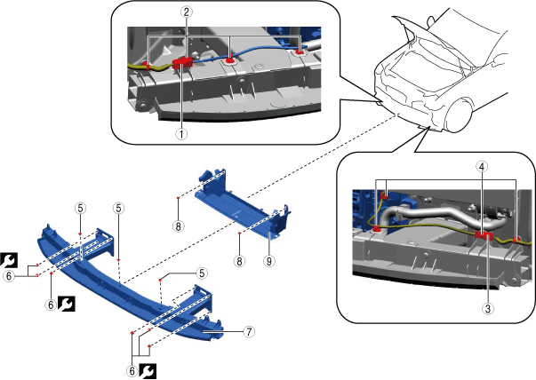
Remove Intake Air Guide (Lower)
1.Remove using the procedure shown in the figure.
azzdjw00003784
|
| Step |
Part name |
Applicable condition |
|
|---|---|---|---|
|
1
|
Connector
|
With active air shutter
|
—
|
|
2
|
Wiring harness clip
|
With active air shutter
|
—
|
|
3
|
Connector
|
T3, e-SKYACTIV PHEV
|
—
|
|
4
|
Wiring harness clip
|
T3, e-SKYACTIV PHEV
|
—
|
|
5
|
Fastener
|
—
|
—
|
|
6
|
Nut
|
—
|
14.5 N·m {1.5 kgf·m, 10.75 ft·lbf}
|
|
7
|
Front cross-member extension assembly
|
—
|
—
|
|
8
|
Fastener
|
—
|
—
|
|
9
|
Intake air guide (lower)
|
—
|
—
|
Wiring harness clip removal note
1.Remove the wiring harness clips as shown in the figure.
azzdjw00003785
|
Intake air guide (lower) removal note
1.Remove the intake air guide (lower) as shown in the figure.
azzdjw00001684
|
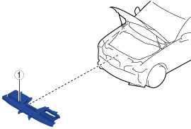
Remove Active Air Shutter
azzdjw00001681
|
1.Remove using the procedure shown in the figure.
azzdjw00001682
|
| Step |
Part name |
|
|---|---|---|
|
1
|
Connector
|
—
|
|
2
|
Wiring harness clip
|
—
|
|
3
|
Fastener
|
—
|
|
4
|
Bolt
|
11 N·m {110 kgf·cm, 95 in·lbf}
|
|
5
|
Bracket
|
—
|
|
6
|
Intake air guide (upper)
|
—
|
|
7
|
Fastener
|
—
|
|
8
|
Seal plate
|
—
|
|
9
|
Bolt
|
11.5 N·m {117 kgf·cm, 102 in·lbf}
|
|
10
|
Lock stay
|
—
|
|
11
|
Fastener
|
—
|
|
12
|
Nut
|
14.5 N·m {1.5 kgf·m, 10.75 ft·lbf}
|
|
13
|
Front crossmember extension and bumper stiffener lower
|
—
|
|
14
|
Fastener
|
—
|
|
15
|
Intake air guide (lower)
|
—
|
|
16
|
Bolt
|
8.5 N·m {85 kgf·cm, 74 in·lbf}
|
|
17
|
Active air shutter
|
—
|
Intake air guide (upper) removal note
1.Remove the intake air guide (upper) as shown in the figure.
azzdjw00001683
|
Intake air guide (lower) removal note
1.Remove the intake air guide (lower) as shown in the figure.
azzdjw00001684
|
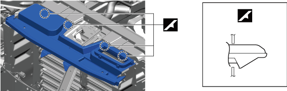
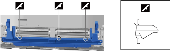
Active air shutter removal note
1.Release the clips shown in the figure and remove the water hose.
azzdjw00001685
|
2.Remove active air shutter.
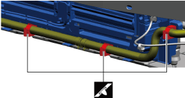
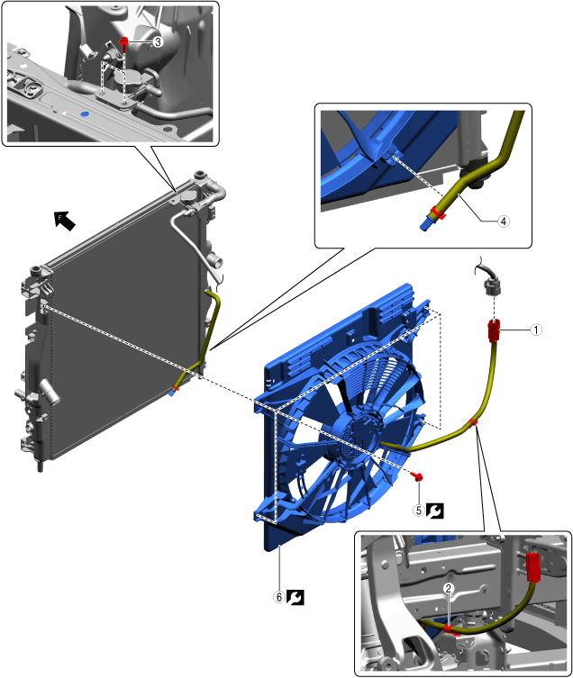
Remove Cooling Fan Motor
1.Remove in the order indicated in the table.
azzdjw00005155
|
| Step |
Part name |
 |
|---|---|---|
|
1
|
Connector
|
—
|
|
2
|
Wiring harness clip
|
—
|
|
3
|
Bolt
|
9.5 N·m {95 kgf·cm, 82 in·lbf}
|
|
4
|
Hose
|
—
|
|
5
|
Bolt
|
8.5 N·m {85 kgf·cm, 74 in·lbf}
|
|
6
|
Cooling fan motor
|
—
|
Remove Radiator
1.Remove in the order indicated in the table.
azzezw00000909
|
| Step |
Part name |
 |
|---|---|---|
|
1
|
Bolt
(See
Bolt removal note)
|
8.5 N·m {85 kgf·cm, 74 in·lbf}
|
|
2
|
Hose
|
—
|
|
3
|
Hose
|
—
|
|
4
|
Bolt
|
8.5 N·m {85 kgf·cm, 74 in·lbf}
|
|
5
|
Radiator
|
—
|
Bolt removal note
1.Secure the condenser to the vehicle body with string.
azzdjw00001681
|
Install in Reverse Order of Removal
1.Install in the reverse order of removal.
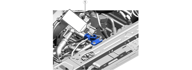
Add Engine Coolant (Main)
1.Add engine coolant (main) to the top surface of the radiator filler port.
azzdjw00007645
|
|
1
|
Bottle
|
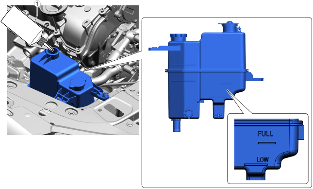
2.Add engine coolant (main) to the coolant reserve tank up to the FULL line.
azzdjw00007652
|
|
1
|
Bottle
|
Total coolant amount (reference)
| Specification |
Capacity |
|---|---|
|
With e-SKYACTIV PHEV
|
8.6 L {9.1 US qt, 7.6 Imp qt}
|
|
Without e-SKYACTIV PHEV
|
7.0 L {7.4 US qt, 6.2 Imp qt}
|
3.After the engine coolant (main) is added up to the FULL line of the coolant reserve tank, add an additional 0.26 L {0.27 US qt, 0.23 Imp qt.}.
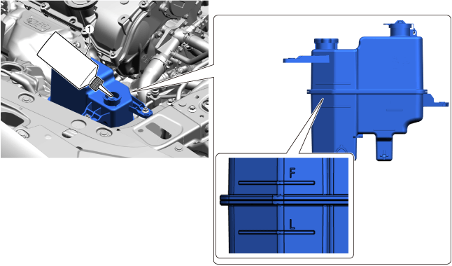
Add Coolant (Sub) [PYUL] (With e-SKYACTIV PHEV)
1.Add coolant (sub) to the coolant reserve tank up to the F line.
azzdjw00007654
|
|
1
|
Bottle
|
Perform Engine Coolant (Main) Air Bleeding (With e-SKYACTIV PHEV)
1.Perform the following procedure switch to compulsory engine start mode.
2.Perform the engine coolant (main) air bleeding using the following procedure.
3.Stop the engine and wait until the engine coolant (main) temperature decreases.
4.If the engine coolant (main) level is low, add engine coolant (main) and inspect the coolant amount.
Bleed Coolant (Sub) Air (With e-SKYACTIV PHEV)
1.Verify that the coolant system cap (sub) is securely closed.
2.Perform the following procedure within 60 s and switch to air bleeding mode.
3.After completing air bleeding mode, verify the height of liquid surface in the coolant reserve tank.
4.Inspect the coolant (sub).
5.If the coolant (sub) level is low, add coolant (sub) and perform air bleeding again.
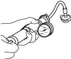
Inspect For Engine Coolant Leakage
1.Install the radiator cap tester to the filling port.
ampjjw00003132
|
2.Apply pressure using the radiator cap tester.
3.When pressurizing the radiator, verify that the pressure is maintained.
Perform Battery Condition Initial Setting (i-Stop Setting)
Circle: Applicable—: Not applicable
| Purpose |
Operation |
Without M Hybrid Boost (With i-stop) |
|
|---|---|---|---|
| T3 |
PYUL |
||
|
1. Verify that the BATT_SOC value measured when the vehicle is in the shop is
75% or more.
|
1. Using the M-MDS, verify that the PID [BATT_SOC] value is
75% or more.
|
O
|
O
|
|
2. In the following cases, perform a battery inspection. (See
BATTERY INSPECTION.)
• [BATT_SOC] value is less than
75%
• [BATT_SOC] value cannot be verified
|
O
|
O
|
|
|
2. Have the [BATT_SOC] value determined by the PCM.
|
1. Disconnect the negative battery terminal and wait for
5 min or more. (See
NEGATIVE BATTERY TERMINAL DISCONNECTION/CONNECTION.)
|
O
|
O
|
|
3. Have the PCM learn the battery condition.
|
1. Connect the negative battery terminal and wait for
10 s or more. (See
NEGATIVE BATTERY TERMINAL DISCONNECTION/CONNECTION.)
|
O
|
O
|
|
2. Switch the ignition ON (engine off) and wait between
15 s to 60 s.
|
O
|
O
|
|
|
3. Press and hold the i-stop OFF switch for
approx.10 s.
|
O
|
O
|
|
|
4. Verify that the i-stop warning light (amber) illumination changes to the i-stop indicator light (green) flashing.
• If the i-stop warning light (amber) does not turn off, it is possible that the procedure was performed incorrectly, therefore, perform the procedure again from the beginning.
• If the i-stop warning light (amber) flashes, perform a battery inspection. (See
BATTERY INSPECTION.)
|
O
|
O
|
|
|
5. Switch ignition OFF.
|
O
|
O
|
|
|
6. Close the hood.
|
O
|
O
|
|
|
4. Perform idle air control learning.
|
1. Switch the ignition ON (engine on).
|
—
|
O
|
|
2. Turn off the following systems to which electrical load is applied.
• Lighting systems such as headlights.
• Climate control system
• Rear window defogger
|
—
|
O
|
|
|
3. Warm up the engine completely.
|
—
|
O
|
|
|
4. Switch the ignition OFF.
|
—
|
O
|
|
|
5. Verify the i-stop control settings.
|
Perform the following procedure from Step 1 to 5 within
25 s.
|
O
|
O
|
|
1. Switch the ignition ON (engine off) and within
5 s, press and hold the i-stop OFF switch for
3 s or more.
|
O
|
O
|
|
|
2. Verify that the i-stop warning light (amber) is on.
|
O
|
O
|
|
|
3. Switch the ignition ON (engine on).
|
O
|
O
|
|
|
4. Verify that the i-stop warning light (amber) illumination changes to the i-stop indicator light (green) flashing.
• If the i-stop warning light (amber) illuminates or flashes, perform a battery inspection. (See
BATTERY INSPECTION.)
|
O
|
O
|
|
|
5. Press and hold the i-stop OFF switch for
approx. 3 s.
|
O
|
O
|
|
|
6. Wait for
30 s while idling (with no electrical load).
|
O
|
O
|
|
|
7. Perform engine racing for a minimum
10 times and a maximum
20 times. Then, wait for
30 s while idling (with no electrical load).
• After the flashing i-stop indicator light (green) turns off, switch the ignition OFF.
• If the i-stop indicator light (green) does not turn off, it is possible that there is a problem with the M Hybrid system, therefore, perform an inspection of the M Hybrid system.
|
—
|
—
|
|
|
8. Maintain the idling condition (with no electrical load) until the i-stop indicator light (green) flashing turns off.
|
O
|
O
|
|
|
9. After the flashing i-stop indicator light (green) turns off, switch the ignition OFF.
|
O
|
O
|
|
|
6. Perform an i-stop control operation verification.
|
1. Switch the ignition ON (engine on).
|
O
|
O
|
|
2. Accelerate to a vehicle speed of
15 km/h in
approx. 5 s without operating the steering wheel.
|
O
|
O
|
|
|
3. Stop the vehicle.
|
O
|
O
|
|
|
4. Verify that the engine stops and restarts by the i-stop control.
|
O
|
O
|
|
|
5. Switch the ignition OFF.
|
O
|
O
|
|
Perform 360° View Monitor System Aiming
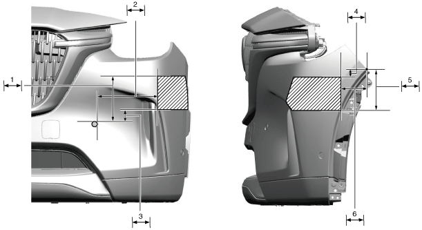
Perform Radar Sensor (Front) Aiming (Without Radar Sensor (Front Side))
Simultaneously Aim Radar Sensor (Front) And (Front Side) (With Radar Sensor (Front Side))
a90uuw00000513
|
| Symbol |
Content |
|---|---|
 |
Radar emitting area
|
 |
118 mm {4.65 in}
|
 |
220 mm {8.66 in}
|
 |
55 mm {2.2 in}
|
 |
35 mm {1.4 in}
|
 |
157 mm {6.18 in}
|
 |
100 mm {3.94 in}
|
Perform Power Liftgate Initialization
1.Close the power liftgate manually.
Initialize Power Outer Mirror Retract/Return Function
Power outer mirrors are in returned position
1.Switch the ignition ON (engine off)/switch the main power ON (READY off).
2.Press the power outer mirror retract/return switch to retract the power outer mirrors.
3.Press the power outer mirror retract/return switch again to return the power outer mirrors.
4.Switch the ignition OFF/switch the main power OFF.
Power outer mirrors are in retracted position
1.Switch the ignition ON (engine off)/switch the main power ON (READY off).
2.Press the power outer mirror retract/return switch 2 times to return the power outer mirrors.
3.Switch the ignition OFF/switch the main power OFF.