 |
ac6wzw00000012
id01121a951300
D-code
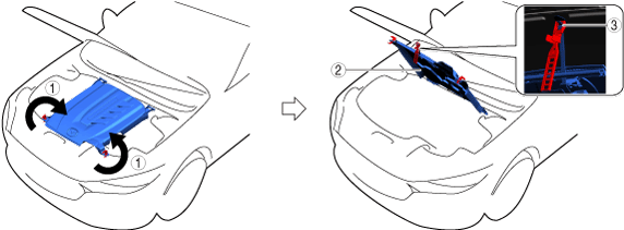
Open Capsule Cover
1.Open in the order indicated in the table.
ac6wzw00000012
|
| Step |
Part name |
|---|---|
|
1
|
Rotating fastener
|
|
2
|
Capsule cover
|
|
3
|
Clip
|
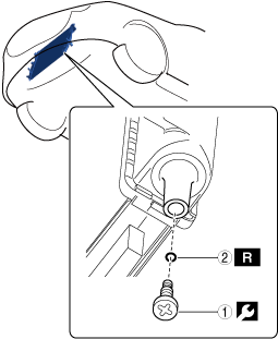
Opening capsule cover note
1.Open the capsule cover as shown in the figure.
ac6wzw00000013
|
| Symbol |
Content |
|---|---|
 |
Servicing procedure
|
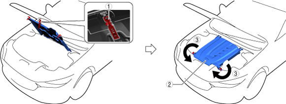
Closing capsule cover note
1.Close the capsule cover as shown in the figure.
ac6wzw00000014
|
| Symbol |
Content |
|---|---|
| |
Servicing procedure
|
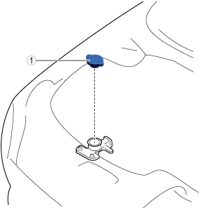
Remove Cooling System Cap (Sub) (PYUL)
1.Remove in the order indicated in the table.
azzdjw00005276
|
| Step |
Part name |
|---|---|
|
1
|
Cooling system cap (sub)
|
Remove Cooling System Cap
1.Remove in the order indicated in the table.
ac6wzw00000094
|
| Step |
Part name |
|---|---|
|
1
|
Cooling system cap
|
Drain Engine Coolant (Main)
1.Open the coolant reserve tank cap.
azzdjw00007646
|
|
1
|
Coolant reserve tank cap
|
2.Drain the engine coolant (main) from the coolant reserve tank.
3.Remove the drain plug (main) and drain the engine coolant (main).
azzdjw00005248
|
|
1
|
Drain plug (main)
|
4.Install the drain plug (main).
Drain EV System Coolant
acxuuw00002056
|
EV system coolant capacity (approx. quantity)
| Capacity |
|---|
|
9.6 L {10 US qt, 8.4 Imp qt}
|
1.Remove the cooling system cap.
ac6wzw00000094
|
|
1
|
Cooling system cap
|
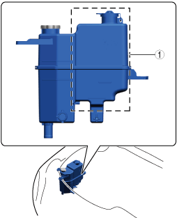
2.Drain the EV system coolant from the coolant reserve tank (sub).
ac6wzw00000095
|
|
1
|
Coolant reserve tank (sub)
|
3.Remove the drain plug (sub).
azzezw00000341
|
| Symbol |
Content |
|---|---|
| |
Servicing procedure
|
 |
1 N·m {11 kgf·cm, 9 in·lbf}
|
 |
Drain cock gasket
|
4.Draining the EV system coolant.
5.Install the radiator drain plug (sub).
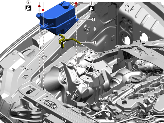
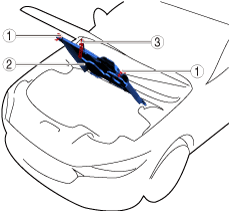
Remove Engine Coolant Reserve Tank
1.Remove using the procedure shown in the figure.
azzdjw00007067
|
| Procedure |
Part name |
 |
|---|---|---|
|
1
|
Bolt
|
9.5 N·m {95 kgf·cm, 82 in·lbf}
|
|
2
|
Nut
|
9.5 N·m {95 kgf·cm, 82 in·lbf}
|
|
3
|
Hose
(See
Hose connection note)
|
—
|
|
4
|
Engine coolant reserve tank
|
—
|
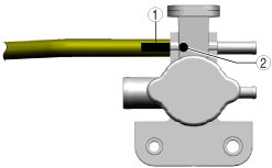
Hose connection note
1.Connect the hose so that the projection is aligned with the marking.
azzdjw00007069
|
| Symbol |
Content |
|---|---|
|
1
|
Marking
|
|
2
|
PROJECTION
|
Install in Reverse Order of Removal
1.Install in the reverse order of removal.
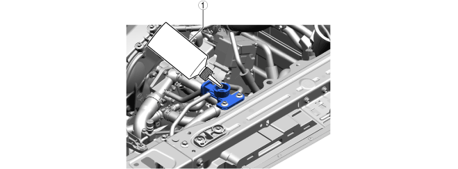
Add Engine Coolant (Main)
1.Add engine coolant (main) to the top surface of the radiator filler port.
azzdjw00007645
|
|
1
|
Bottle
|
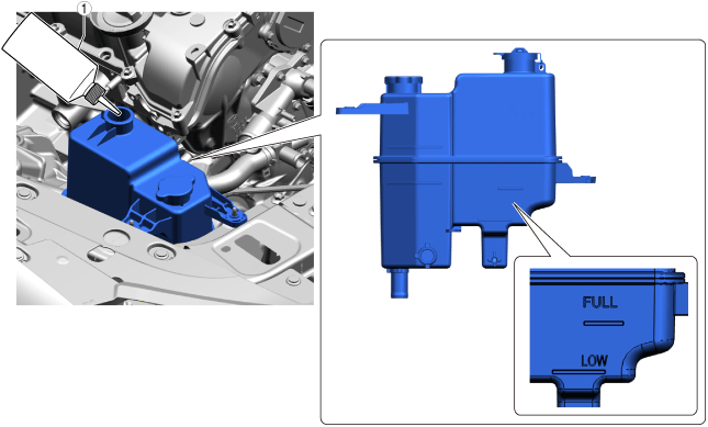
2.Add engine coolant (main) to the coolant reserve tank up to the FULL line.
azzdjw00007652
|
|
1
|
Bottle
|
Total coolant amount (reference)
| Specification |
Capacity |
|---|---|
|
With e-SKYACTIV PHEV
|
8.6 L {9.1 US qt, 7.6 Imp qt}
|
|
Without e-SKYACTIV PHEV
|
7.0 L {7.4 US qt, 6.2 Imp qt}
|
3.After the engine coolant (main) is added up to the FULL line of the coolant reserve tank, add an additional 0.26 L {0.27 US qt, 0.23 Imp qt.}.
Perform Engine Coolant (Main) Air Bleeding (With e-SKYACTIV PHEV)
1.Perform the following procedure switch to compulsory engine start mode.
2.Perform the engine coolant (main) air bleeding using the following procedure.
3.Stop the engine and wait until the engine coolant (main) temperature decreases.
4.If the engine coolant (main) level is low, add engine coolant (main) and inspect the coolant amount.
Bleed Coolant (Sub) Air (With e-SKYACTIV PHEV)
1.Verify that the coolant system cap (sub) is securely closed.
2.Perform the following procedure within 60 s and switch to air bleeding mode.
3.After completing air bleeding mode, verify the height of liquid surface in the coolant reserve tank.
4.Inspect the coolant (sub).
5.If the coolant (sub) level is low, add coolant (sub) and perform air bleeding again.
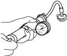
Inspect For Engine Coolant Leakage
1.Install the radiator cap tester to the filling port.
ampjjw00003132
|
2.Apply pressure using the radiator cap tester.
3.When pressurizing the radiator, verify that the pressure is maintained.
Install cooling system cap (sub)
1.Remove in the order indicated in the table.
azzdjw00005277
|
| Step |
Part name |
|---|---|
|
1
|
Cooling system cap (sub)
|
Install cooling system cap
1.Install in the order indicated in the table.
ac6wzw00000094
|
| Step |
Part name |
|---|---|
|
1
|
Cooling system cap
|