WARNING:
When working near the engine room while the engine has started or the ignition switch is ON, do not touch the rotating co
such as the V-ribbed belt or cooling fan.
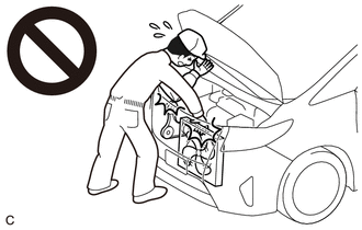
Image 1
Touching the rotating components such as the V-ribbed belt or cooling fan. could result in your hand or clothing getting ca
pulled in.
PROCEDURE
1. INSPECT ENGINE COOLANT
Refer to ON-VEHICLE INSPECTION [01/2019 - ]
2. INSPECT ENGINE OIL
Refer to ON-VEHICLE INSPECTION [01/2019 - ]
3. INSPECT BATTERY
Refer to ON-VEHICLE INSPECTION [01/2019 - ]
4. INSPECT AIR CLEANER FILTER ELEMENT SUB-ASSEMBLY
Refer to REMOVAL [01/2019 - ]
5. INSPECT SPARK PLUG
Refer to ON-VEHICLE INSPECTION [01/2019 - ]
6. INSPECT V-RIBBED BELT
See step 1
7. INSPECT VALVE AND ADJUSTER NOISE
a. Rev up the engine several times. Check that the engine does not emit unusual noises.
b. If unusual noises occur, warm up the engine and idle it for 30 minutes or more, then perform the inspection.
HINT:
If any defects or problems are found during the inspection, perform valve lash adjuster assembly inspection.
Refer to PROCEDURE - Step 2
8. INSPECT IGNITION TIMING
Standard Ignition Timing
0 to 14В° BTDC at idle
f. Check that the ignition timing advances immediately when the engine speed is increased.
g. Enter the following menus: Powertrain / Engine and ECT / Active Test / Connect the TC and TE1 / ON.
Powertrain > Engine and ECT > Active Test
Active Test Display
Connect the TC and TE1
Data List Display
IGN Advance
h. Monitor IGN Advance of the Data List.
Standard Ignition Timing
8 to 12В° BTDC at idle
NOTE:
When checking the ignition timing, the transaxle should be in neutral or park.
9. INSPECT ENGINE IDLE SPEED
NOTE:
Turn off all electrical systems and the A/C.
Inspect the engine idle speed with the cooling fan off.
When checking the engine idle speed, the transaxle should be in neutral or park.
a. Warm up and stop the engine.
b. Connect the Techstream to the DLC3.
c. Start the engine and run it at idle.
d. Turn the Techstream on.
e. Enter the following menus: Powertrain / Engine and ECT / Data List / Engine Speed.
Powertrain > Engine and ECT > Data List
Tester Display
Engine Speed
f. Read the value displayed on the Techstream.
Standard Idle Speed
for CVT
700 to 800 rpm
for Manual Transaxle
600 to 700 rpm
10. INSPECT COMPRESSION
NOTE:
Keep the spark plug holes free of foreign matter when measuring the compression pressure.
a. Warm up and stop the engine.
b. Check for DTCs.
Refer to DTC CHECK / CLEAR [01/2019 - 03/2019] , or refer to DTC CHECK / CLEAR [03/2019 - ]
c. Remove the 4 spark plugs.
Refer to REMOVAL [01/2019 - ]
d. Disconnect the 4 fuel injector connectors.
NOTE:
Disable fuel injection in order to prevent catalyst damage due to unburned gasoline.
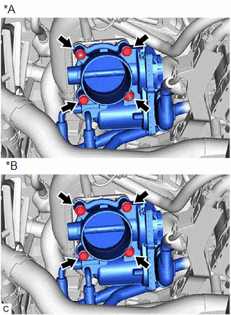
Image 2
*A
w/ Stud Bolt
*B
w/o Stud Bolt
1. Remove the 2 bolts, 2 nuts and separate the throttle body assembly from the intake manifold.
g. w/o Stud Bolt:
1. Remove the 4 bolts and separate the throttle body assembly from the intake manifold.
h. Check the cylinder compression pressure.
1. Insert a compression gauge into the spark plug hole.
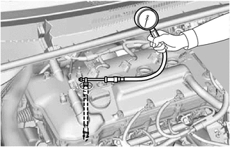
Image 3
2. While cranking the engine, measure the compression pressure.
3. If the cylinder compression pressure is low, pour a small amount of engine oil into the cylinder through the spark plug hole and inspect it again.
HINT:
If adding engine oil increases the compression pressure, the piston rings and/or cylinder bore may be worn or damaged.
If the compression pressure stays low, a valve may be stuck or seated improperly, or there may be leaks in the cylinder head gasket.
i. w/ Stud Bolt:
1. Install a new throttle body gasket and the throttle body assembly to the intake manifold with the 2 bolts and 2 nuts.
Torque: 10 N*m (102 kgf*cm, 7 ft.*lbf)
NOTE:
If the throttle body assembly has been struck or dropped, replace it.
j. w/o Stud Bolt:
1. Install a new throttle body gasket and the throttle body assembly to the intake manifold with the 4 bolts.
Torque: 10 N*m (102 kgf*cm, 7 ft.*lbf)
NOTE:
If the throttle body assembly has been struck or dropped, replace it.
k. Install the air cleaner cap with air cleaner hose.
Refer to PROCEDURE - Step 3
l. Connect the 4 fuel injector connectors.
m. Install the 4 spark plugs.
Refer to INSTALLATION [01/2019 - ]
n. Clear the DTCs.
Refer to DTC CHECK / CLEAR [01/2019 - 03/2019] , or refer to DTC CHECK / CLEAR [03/2019 - ]
NOTE:
After the inspection, clear the DTCs, check for DTCs again and make sure the normal system code is output.
11. INSPECT CO/HC
HINT:
This check determines whether or not the idle CO/HC complies with regulations.
a. Start the engine.
b. Keep the engine at 2500 rpm for approximately 180 seconds.
c. Insert a CO/HC meter testing probe at least 40 cm (1.3 ft.) into the tailpipe during idle.
d. Immediately check the CO/HC concentration during idle and when the engine is running at 2500 rpm.
HINT:
When doing a 2 mode (with the engine idling/running at 2500 rpm) test, the measurement procedures are determined by applicable local regulations.
If the CO/HC concentration does not comply with the regulations, perform troubleshooting in the order given below.
1. Check for DTCs.
Refer to DTC CHECK / CLEAR [01/2019 - 03/2019] , or refer to DTC CHECK / CLEAR [03/2019 - ]
2. See the following table for possible causes, then inspect the applicable parts and repair them if necessary.
CO
HC
Problem
Possible Cause
Normal
High
Rough idle
a. Faulty ignition:
Incorrect timing
Fouled, shorted or improperly gapped p
b. Incorrect valve clearance
c. Leaks in intake or exhaust valves
d. Leaks in cylinders
a. Vacuum leaks:
DRIVE BELT
COMPONENTS [01/2019 - ]
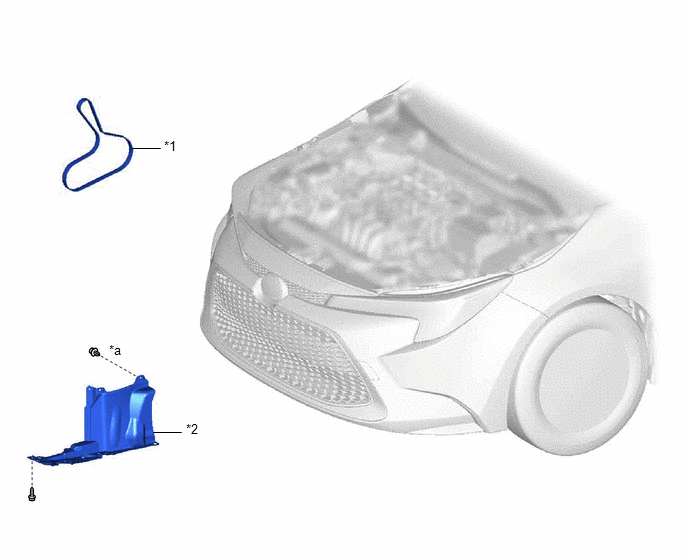
Image 4
Fig. 1: Drive Belt Replacement Components
Courtesy of В© TOYOTA, LICENSE AGREEMENT TMS1002
*1
V-RIBBED BELT
*2
REAR ENGINE UNDER COVER RH
*a
Type A: x 7
Type B: x 8
-
-
ON-VEHICLE INSPECTION [01/2019 - ]
PROCEDURE
1. INSPECT V-RIBBED BELT
a. Check the V-ribbed belt for wear, cracks or other signs of damage.
HINT:
If any of the following defects is found, replace the V-ribbed belt.
The V-ribbed belt is cracked.
The V-ribbed belt is worn out to the extent that the cords are exposed.
The V-ribbed belt has chunks missing from the ribs.
b. Check that the V-ribbed belt fits properly in the ribbed grooves.
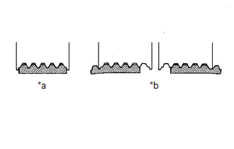
Image 5
*a
Correct
*b
Incorrect
HINT:
Check with your hand to confirm that the V-ribbed belt has not slipped out of the grooves on the bottom of the pulley. If it has slipped out, replace the V-rib
a new V-ribbed belt correctly.
REMOVAL [01/2019 - ]
PROCEDURE
1. REMOVE REAR ENGINE UNDER COVER RH
Refer to PROCEDURE - Step 1
2. REMOVE V-RIBBED BELT
Refer to PROCEDURE - Step 2
INSTALLATION [01/2019 - ]
PROCEDURE
1. INSTALL V-RIBBED BELT
Refer to PROCEDURE - Step 1
2. INSPECT V-RIBBED BELT
See step 1
3. INSTALL REAR ENGINE UNDER COVER RH
Refer to PROCEDURE - Step 3
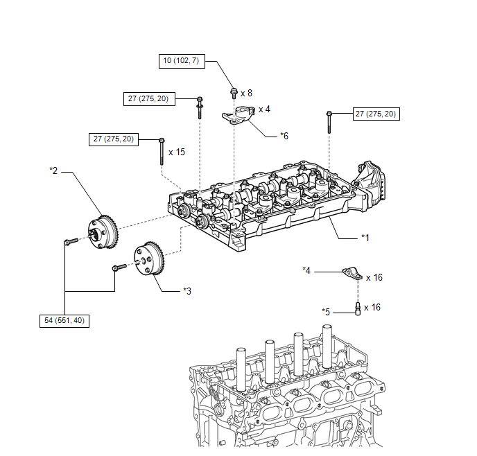
Image 6
Fig. 2: Camshaft Replacement Components With Torque Specifications
Courtesy of В© TOYOTA, LICENSE AGREEMENT TMS1002
*1
CAMSHAFT HOUSING SUB-
ASSEMBLY
*2
CAMSHAFT TIMING EXHAUST GE
ASSEMBLY
*3
CAMSHAFT TIMING GEAR ASSEMBLY
*4
NO. 1 VALVE ROCKER ARM SUB-
ASSEMBLY
*5
VALVE LASH ADJUSTER ASSEMBLY
*6
VALVE ROCKER ARM LOST MOTI
DAMPER SUB-ASSEMBLY

Image 7
N*m (kgf*cm, ft.*lbf): Specified torque
-
-
REMOVAL [01/2019 - 03/2019]
CAUTION / NOTICE / HINT
The necessary procedures (adjustment, calibration, initialization, or registration) that must be performed after parts are removed and installed, or replaced during camsha
removal/installation are shown below.
NECESSARY PROCEDURES AFTER PARTS REMOVED/INSTALLED/REPLACED
Replaced Part or Performed Procedure
Necessary Procedure
Effect/Inoperative Function when
Necessary Procedure not Performed
Link
Battery terminal is disconnected/reconnected
Perform steering sensor zero point calibration
Lane Control System
Refer to INITIALIZAT
[06/2018 - ]
Pre-collision System
Lighting System (w/ AFS) (EXT)
Replacement of ECM
Vehicle Identification Number (VIN)
registration
MIL comes on
Refer to REGISTRATI
Replacement of ECM*1
Code registration (Smart Key System (for
Gasoline Model, Start Function))
Wireless Door Lock Control System
(for Gasoline Model with Smart Key
System)
Smart Key System (for Gasoline
Model, Entry Function)
Smart Key System (for Gasoline
Model, Start Function)
Steering lock function
Refer to REGISTRATI
[01/2019 - 09/2019]
Replacement of ECM*2
Code registration (Immobiliser system)
Engine start
Refer to REGISTRATI
[01/2019 - 09/2019]
Replacement of throttle body assembly
Replacement of engine assembly
Replacement of camshaft timing gear
assembly
Replacement of camshaft timing exhaust
gear assembly
Replacement of fuel injector assembly
Replacement of ignition coil assembly
Gas leak from exhaust system is repaired
Replacement of continuously variable
valve lift controller assembly
Inspection After Repair
Poor idle, etc.
Engine start function, etc.
Refer to INITIALIZAT
[01/2019 - ]
Suspension, tires, etc.
(The vehicle height changes because of
suspension or tire replacement)
Perform headlight ECU sub-assembly LH
initialization
Lighting system (w/ AFS) (EXT)
Refer to INITIALIZAT
[06/2018 - ]
Front wheel alignment adjustment
1. Perform "Reset Memory".
2. Perform acceleration sensor zero point
calibration and store system
information memorization.
VSC is disabled or malfunctions
DTCs are output
Slip indicator light illuminates
ABS warning light illuminates
w/ Electric Parking Bra
System: Refer to UTILI
[06/2018 - ]
w/o Electric Parking Br
System: Refer to UTILI
[01/2019 - 03/2019]
CVT fluid
ATF thermal degradation estimate reset
The value of the Data List item "ATF
Thermal Degradation Estimate" is not
estimated correctly
Refer to INITIALIZAT
[01/2019 - ] for K313
*1: w/ Smart Key System
*2: w/o Smart Key System
NOTE:
After the ignition switch is turned off, the radio and display receiver assembly records various types of memory and settin
result, after turning the ignition switch off, make sure to wait at least 85 seconds before disconnecting the cable from the n
battery terminal. (for Audio and Visual System (for Gasoline Model))
After the engine switch is turned off, the radio and display receiver assembly records various types of memory and setting
result, after turning the engine switch off, make sure to wait at least 85 seconds before disconnecting the cable from the ne
battery terminal. (for Navigation System)
PROCEDURE
1. REMOVE CHAIN SUB-ASSEMBLY
Refer to REMOVAL [01/2019 - 03/2019]
2. INSPECT CAMSHAFT TIMING GEAR ASSEMBLY
Refer to PROCEDURE - Step 31
3. INSPECT CAMSHAFT TIMING EXHAUST GEAR ASSEMBLY
Refer to PROCEDURE - Step 32
4. REMOVE CAMSHAFT TIMING GEAR ASSEMBLY
Refer to PROCEDURE - Step 33
5. REMOVE CAMSHAFT TIMING EXHAUST GEAR ASSEMBLY
Refer to PROCEDURE - Step 34
6. REMOVE VALVE ROCKER ARM LOST MOTION DAMPER SUB-ASSEMBLY
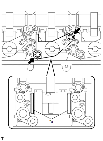
Image 8
*a
Shim
NOTE:
Make sure the camshaft housing sub-assembly is installed to the cylinder head sub-assembly when removing o
valve rocker arm lost motion damper sub-assembly.
If a valve rocker arm lost motion damper sub-assembly is removed, do not remove the camshaft housing sub-as
Do not remove the shims. If a shim is removed, replace the camshaft housing sub-assembly as engine malfunct
result from irregular valve timing.
7. INSTALL VALVE ROCKER ARM LOST MOTION DAMPER SUB-ASSEMBLY
a. Install the 4 valve rocker arm lost motion damper sub-assemblies with the 8 bolts. Uniformly tighten the bolts.

Image 9
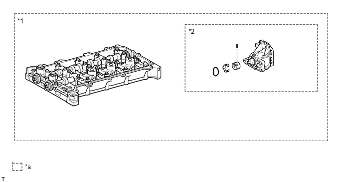
Image 10
*1
Camshaft Housing Sub-assembly
*2
Continuously Variable Valve Lift Co
Assembly
*a
Set of parts that are replaced together
-
-
a. Uniformly loosen and remove the 17 bearing cap bolts in the order shown in the illustration.
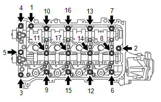
Image 11
Fig. 3: Camshaft Housing Sub-Assembly Loosening Sequence
Courtesy of В© TOYOTA, LICENSE AGREEMENT TMS1002
NOTE:
Uniformly loosen the bearing cap bolts while keeping the camshaft housing level.
b. Using a screwdriver, remove the camshaft housing sub-assembly by prying between the cylinder head sub-assembly and camshaft housing sub-assembly.
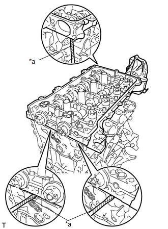
Image 12
*a
Protective Tape
NOTE:
Be careful not to damage the contact surfaces of the cylinder head sub-assembly and camshaft housing sub-assemb
HINT:
Tape the screwdriver tip before use.
9. REMOVE NO. 1 VALVE ROCKER ARM SUB-ASSEMBLY
Refer to PROCEDURE - Step 39
10. REMOVE VALVE LASH ADJUSTER ASSEMBLY
Refer to PROCEDURE - Step 40
11. INSPECT NO. 1 VALVE ROCKER ARM SUB-ASSEMBLY
Refer to PROCEDURE - Step 1
12. INSPECT VALVE LASH ADJUSTER ASSEMBLY
Refer to PROCEDURE - Step 2
REMOVAL [03/2019 - ]
CAUTION / NOTICE / HINT
The necessary procedures (adjustment, calibration, initialization, or registration) that must be performed after parts are removed and installed, or replaced during camsha
removal/installation are shown below.
NECESSARY PROCEDURES AFTER PARTS REMOVED/INSTALLED/REPLACED
Replaced Part or Performed Procedure
Necessary Procedure
Effect/Inoperative Function when
Necessary Procedure not Performed
Link
Battery terminal is disconnected/reconnected
Perform steering sensor zero point calibration
Lane Control System
Refer to INITIALIZAT
Replacement of ECM*1
Code registration (Smart Key System (for
Gasoline Model, Start Function))
Wireless Door Lock Control System
(for Gasoline Model with Smart Key
System)
Smart Key System (for Gasoline
Model, Entry Function)
Smart Key System (for Gasoline
Model, Start Function)
Steering lock function
| Refer to | REGISTRATI |
|---|---|
| [01/2019 - 09/2019] | , or |
| to | REGISTRATION [09 |
- 04/2020] , or refer t
REGISTRATION [04/20
Replacement of ECM*2
Code registration (Immobiliser system)
Engine start
| Refer to | REGISTRATI |
|---|---|
| [01/2019 - 09/2019] | , or |
| to | REGISTRATION [09 |
- 04/2020] , or refer t
REGISTRATION [04/20
Replacement of throttle body assembly
Replacement of engine assembly
Replacement of camshaft timing gear
assembly
Replacement of camshaft timing exhaust
gear assembly
Replacement of fuel injector assembly
Replacement of ignition coil assembly
Gas leak from exhaust system is repaired
Replacement of continuously variable
valve lift controller assembly
Inspection After Repair
Poor idle, etc.
Engine start function, etc.
Refer to INITIALIZAT
[01/2019 - ]
Suspension, tires, etc.
(The vehicle height changes because of
suspension or tire replacement)
Perform headlight ECU sub-assembly LH
initialization
Lighting system (w/ AFS) (EXT)
Refer to INITIALIZAT
[06/2018 - ]
Front wheel alignment adjustment
1. Perform "Reset Memory".
2. Perform acceleration sensor zero point
calibration and store system
information memorization.
VSC is disabled or malfunctions
DTCs are output
Slip indicator light illuminates
ABS warning light illuminates
w/ Electric Parking Bra
System: Refer to UTILI
[06/2018 - ]
w/o Electric Parking Br
System: Refer to UTILI
[03/2019 - ]
CVT fluid
ATF thermal degradation estimate reset
The value of the Data List item "ATF
Thermal Degradation Estimate" is not
estimated correctly
Refer to INITIALIZAT
[01/2019 - ] for K313
*1: w/ Smart Key System
*2: w/o Smart Key System
NOTE:
After the ignition switch is turned off, the radio and display receiver assembly records various types of memory and settings. As
after turning the ignition switch off, make sure to wait at least 85 seconds before disconnecting the cable from the negative (-) b
terminal. (for Navigation System and Audio and Visual System (for Gasoline Model))
PROCEDURE
1. REMOVE CHAIN SUB-ASSEMBLY
Refer to REMOVAL [03/2019 - ]
2. INSPECT CAMSHAFT TIMING GEAR ASSEMBLY
Refer to PROCEDURE - Step 32
3. INSPECT CAMSHAFT TIMING EXHAUST GEAR ASSEMBLY
Refer to PROCEDURE - Step 33
4. REMOVE CAMSHAFT TIMING GEAR ASSEMBLY
Refer to PROCEDURE - Step 34
5. REMOVE CAMSHAFT TIMING EXHAUST GEAR ASSEMBLY
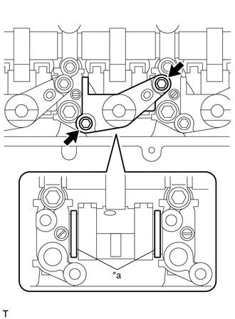
Image 13
*a
Shim
NOTE:
Make sure the camshaft housing sub-assembly is installed to the cylinder head sub-assembly when removing o
valve rocker arm lost motion damper sub-assembly.
If a valve rocker arm lost motion damper sub-assembly is removed, do not remove the camshaft housing sub-as
Do not remove the shims. If a shim is removed, replace the camshaft housing sub-assembly as engine malfunct
result from irregular valve timing.
7. INSTALL VALVE ROCKER ARM LOST MOTION DAMPER SUB-ASSEMBLY
a. Install the 4 valve rocker arm lost motion damper sub-assemblies with the 8 bolts. Uniformly tighten the bolts.
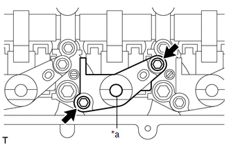
Image 14
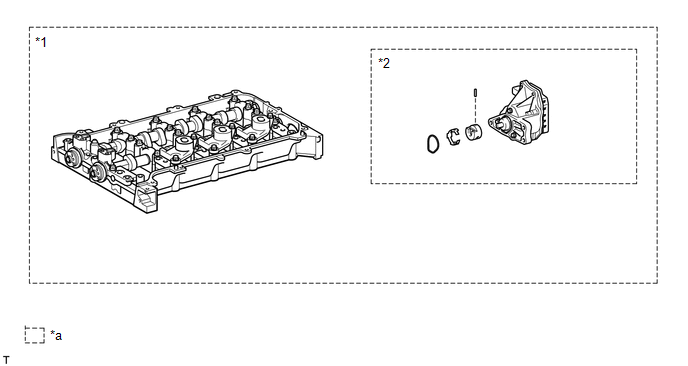
Image 15
*1
Camshaft Housing Sub-assembly
*2
Continuously Variable Valve Lift Co
Assembly
*a
Set of parts that are replaced together
-
-
a. Uniformly loosen and remove the 17 bearing cap bolts in the order shown in the illustration.
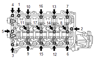
Image 16
NOTE:
Uniformly loosen the bearing cap bolts while keeping the camshaft housing level.
b. Using a screwdriver, remove the camshaft housing sub-assembly by prying between the cylinder head sub-assembly and camshaft housing sub-assembly.
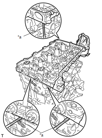
Image 17
*a
Protective Tape
NOTE:
Be careful not to damage the contact surfaces of the cylinder head sub-assembly and camshaft housing sub-assemb
HINT:
Tape the screwdriver tip before use.
9. REMOVE NO. 1 VALVE ROCKER ARM SUB-ASSEMBLY
Refer to PROCEDURE - Step 40
10. REMOVE VALVE LASH ADJUSTER ASSEMBLY
Refer to PROCEDURE - Step 41
11. INSPECT NO. 1 VALVE ROCKER ARM SUB-ASSEMBLY
Refer to PROCEDURE - Step 1
12. INSPECT VALVE LASH ADJUSTER ASSEMBLY
Refer to PROCEDURE - Step 2
INSTALLATION [01/2019 - ]
CAUTION / NOTICE / HINT
HINT:
Perform "Inspection After Repair" after replacing the camshaft housing sub-assembly, camshaft timing gear assembly or camshaft timing exhaust gear assembly.
Refer to INITIALIZATION [01/2019 - ]
PROCEDURE
1. INSTALL VALVE LASH ADJUSTER ASSEMBLY
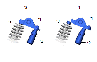
Image 18
*1
No. 1 Valve Rocker Arm Sub-assembly
*2
Valve Lash Adjuster Assembly
*3
Valve Stem Cap
*a
Correct
*b
Incorrect
b. Apply seal packing in a continuous line as shown in the illustration.
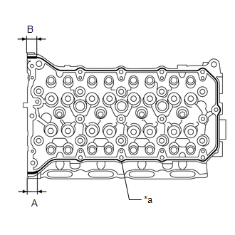
Image 19
*a
Continuous line
Seal Packing
Toyota Genuine Seal Packing Black, Three Bond 1207B or equivalent
Seal Packing Application Chart
Area
Seal Packing Diameter
Application length
Continuous line
3.5 to 4.5 mm (0.138 to 0.177 in.)
-
(A)
8.0 mm (0.315 in.)
15 mm (0.591 in.)
(B)
7.0 mm (0.276 in.)
15 mm (0.591 in.)
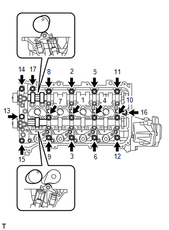
Image 20
Fig. 4: Camshaft Housing Sub-Assembly Tightening Sequence
Courtesy of В© TOYOTA, LICENSE AGREEMENT TMS1002
d. Install the camshaft housing sub-assembly with the 17 bolts and tighten them in the order shown in the illustration.
Torque: 27 N*m (275 kgf*cm, 20 ft.*lbf)
NOTE:
After installing the camshaft housing sub-assembly, make sure that the cam lobes are positioned as shown in th
illustration.
If any of the bolts are loosened during installation, remove the camshaft housing sub-assembly, clean the instal
surfaces, and reapply seal packing.
If the camshaft housing sub-assembly is removed because any of the bolts are loosened during installation, ma
the previously applied seal packing does not enter any oil passages.
After installing the camshaft housing sub-assembly, wipe off any seal packing that seeped out from between the
housing sub-assembly and cylinder head sub-assembly.
HINT:
Perform "Inspection After Repair" after replacing the camshaft housing sub-assembly.
| Refer to | INITIALIZATION [01/2019 - ] |
|---|---|
| 4. | INSTALL CAMSHAFT TIMING GEAR ASSEMBLY |
Refer to PROCEDURE - Step 19 [01/2019 - 03/2019] , or refer to PROCEDURE - Step 19 [03/2019 - ]
5. INSTALL CAMSHAFT TIMING EXHAUST GEAR ASSEMBLY
Refer to PROCEDURE - Step 18 [01/2019 - 03/2019] , or refer to PROCEDURE - Step 18 [03/2019 - ]
6. INSTALL CHAIN SUB-ASSEMBLY
Refer to INSTALLATION [01/2019 - 03/2019] , or refer to INSTALLATION [03/2019 - ]
CYLINDER HEAD GASKET
COMPONENTS [01/2019 - ]
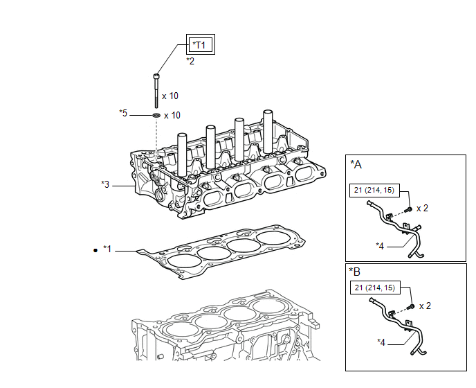
Image 21
Fig. 5: Cylinder Head Gasket Replacement Components With Torque Specifications
Courtesy of В© TOYOTA, LICENSE AGREEMENT TMS1002
*A
for CVT
*B
for M
Trans
*1
CYLINDER HEAD
GASKET
*2
CYLI
HEAD
BOLT
*3
CYLINDER HEAD SUB-
ASSEMBLY
*4
NO. 1
WATE
BY-PA
PIPE
*5
PLATE WASHER
-

Image 22
Tightening torque for
"Major areas involving
basic vehicle performance
such as
moving/turning/stopping":
N*m (kgf*cm, ft.*lbf)

Image 23
N*m
(kgf*c
ft.*lbf
Speci
torque
•
Non-reusable part
-
*T1
1st: 49 (500, 36)
2nd: Turn 90В°
3rd: Turn 45В°
-
REMOVAL [01/2019 - 03/2019]
CAUTION / NOTICE / HINT
The necessary procedures (adjustment, calibration, initialization, or registration) that must be performed after parts are removed and installed, or replaced during cylinde
removal/installation are shown below.
NECESSARY PROCEDURES AFTER PARTS REMOVED/INSTALLED/REPLACED
Replaced Part or Performed Procedure
Necessary Procedure
Effect/Inoperative Function when
Necessary Procedure not Performed
Link
Replacement of ECM*1
Code registration (Smart Key System (for
Gasoline Model, Start Function))
Wireless Door Lock Control System
(for Gasoline Model with Smart Key
System)
Smart Key System (for Gasoline
Model, Entry Function)
Smart Key System (for Gasoline
Model, Start Function)
Steering lock function
Refer to REGISTRATI
[01/2019 - 09/2019]
Replacement of ECM*2
Code registration (Immobiliser system)
Engine start
Refer to REGISTRATI
[01/2019 - 09/2019]
Replacement of throttle body assembly
Replacement of engine assembly
Replacement of cylinder head sub-
assembly
Replacement of camshaft timing gear
assembly
Replacement of camshaft timing exhaust
gear assembly
Replacement of fuel injector assembly
Replacement of ignition coil assembly
Gas leak from exhaust system is repaired
Inspection After Repair
Poor idle, etc.
Engine start function, etc.
Refer to INITIALIZAT
[01/2019 - ]
Suspension, tires, etc.
(The vehicle height changes because of
suspension or tire replacement)
Perform headlight ECU sub-assembly LH
initialization
Lighting system (w/ AFS) (EXT)
Refer to INITIALIZAT
[06/2018 - ]
Front wheel alignment adjustment
1. Perform "Reset Memory".
2. Perform acceleration sensor zero point
calibration and store system
information memorization.
VSC is disabled or malfunctions
DTCs are output
Slip indicator light illuminates
ABS warning light illuminates
w/ Electric Parking Bra
System: Refer to UTILI
[06/2018 - ]
w/o Electric Parking Br
System: Refer to UTILI
[01/2019 - 03/2019]
CVT fluid
ATF thermal degradation estimate reset
The value of the Data List item "ATF
Thermal Degradation Estimate" is not
estimated correctly
Refer to INITIALIZAT
[01/2019 - ] for K313
*1: w/ Smart Key System
*2: w/o Smart Key System
NOTE:
After the ignition switch is turned off, the radio and display receiver assembly records various types of memory and settin
result, after turning the ignition switch off, make sure to wait at least 85 seconds before disconnecting the cable from the n
battery terminal. (for Audio and Visual System (for Gasoline Model))
After the engine switch is turned off, the radio and display receiver assembly records various types of memory and setting
result, after turning the engine switch off, make sure to wait at least 85 seconds before disconnecting the cable from the ne
battery terminal. (for Navigation System)
PROCEDURE
1. REMOVE CAMSHAFT HOUSING SUB-ASSEMBLY
Refer to REMOVAL [01/2019 - 03/2019]
2. REMOVE NO. 1 WATER BY-PASS PIPE
See step 15
3. REMOVE CYLINDER HEAD SUB-ASSEMBLY
a. Using a 10 mm bi-hexagon socket wrench, uniformly loosen and remove the 10 cylinder head set bolts and 10 cylinder head set plate washers in several ste
shown in the illustration.
Fig. 6: Cylinder Head Sub-Assembly Loosening Sequence
Courtesy of В© TOYOTA, LICENSE AGREEMENT TMS1002
NOTE:
Do not drop the cylinder head set plate washers into the cylinder head sub-assembly.
Removing the cylinder head set bolts in the incorrect order may cause warpage or cracking of the cylinder head
assembly.
HINT:
Arrange the removed parts in such a way that they can be reinstalled to their original locations.
b. Remove the cylinder head sub-assembly from the cylinder block sub-assembly.
4. REMOVE CYLINDER HEAD GASKET
a. Remove the cylinder head gasket from the cylinder block sub-assembly.
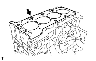
Image 24
5. INSPECT CYLINDER HEAD FOR FLATNESS
Refer to PROCEDURE - Step 1
6. INSPECT CYLINDER HEAD SET BOLT
Refer to PROCEDURE - Step 15
REMOVAL [03/2019 - ]
CAUTION / NOTICE / HINT
The necessary procedures (adjustment, calibration, initialization, or registration) that must be performed after parts are removed and installed, or replaced during cylinde
removal/installation are shown below.
NECESSARY PROCEDURES AFTER PARTS REMOVED/INSTALLED/REPLACED
Replaced Part or Performed Procedure
Necessary Procedure
Effect/Inoperative Function when
Necessary Procedure not Performed
Link
Battery terminal is disconnected/reconnected
Perform steering sensor zero point calibration
Lane Control System
Refer to INITIALIZAT
[06/2018 - ]
Pre-collision System
Lighting System (w/ AFS) (EXT)
Replacement of ECM
Vehicle Identification Number (VIN)
registration
MIL comes on
Refer to REGISTRATI
[01/2019 - ]
ECU communication ID registration
(Immobiliser system)
Engine start function
| Refer to | REGISTRATI |
|---|---|
| [01/2019 - 09/2019] | , or |
| to | REGISTRATION [09 |
- 04/2020] , or refer t
REGISTRATION [04/20
1. Reset memory
2. Deceleration sensor zero point
Replacement of ECM*2
Code registration (Immobiliser system)
Engine start
| Refer to | REGISTRATI |
|---|---|
| [01/2019 - 09/2019] | , or |
| to | REGISTRATION [09 |
- 04/2020] , or refer t
REGISTRATION [04/20
Replacement of throttle body assembly
Replacement of engine assembly
Replacement of cylinder head sub-
assembly
Replacement of camshaft timing gear
assembly
Replacement of camshaft timing exhaust
gear assembly
Replacement of fuel injector assembly
Replacement of ignition coil assembly
Gas leak from exhaust system is repaired
Inspection After Repair
Poor idle, etc.
Engine start function, etc.
Refer to INITIALIZAT
[01/2019 - ]
Suspension, tires, etc.
(The vehicle height changes because of
suspension or tire replacement)
Perform headlight ECU sub-assembly LH
initialization
Lighting system (w/ AFS) (EXT)
Refer to INITIALIZAT
[06/2018 - ]
Front wheel alignment adjustment
1. Perform "Reset Memory".
2. Perform acceleration sensor zero point
calibration and store system
information memorization.
VSC is disabled or malfunctions
DTCs are output
Slip indicator light illuminates
ABS warning light illuminates
w/ Electric Parking Bra
System: Refer to UTILI
[06/2018 - ]
w/o Electric Parking Br
System: Refer to UTILI
[03/2019 - ]
CVT fluid
ATF thermal degradation estimate reset
The value of the Data List item "ATF
Thermal Degradation Estimate" is not
estimated correctly
Refer to INITIALIZAT
[01/2019 - ] for K313
*1: w/ Smart Key System
*2: w/o Smart Key System
NOTE:
After the ignition switch is turned off, the radio and display receiver assembly records various types of memory and settings. As
after turning the ignition switch off, make sure to wait at least 85 seconds before disconnecting the cable from the negative (-) b
terminal. (for Navigation System and Audio and Visual System (for Gasoline Model))
PROCEDURE
1. REMOVE CAMSHAFT HOUSING SUB-ASSEMBLY
Refer to REMOVAL [03/2019 - ]
2. REMOVE NO. 1 WATER BY-PASS PIPE
See step 15
3. REMOVE CYLINDER HEAD SUB-ASSEMBLY
a. Using a 10 mm bi-hexagon socket wrench, uniformly loosen and remove the 10 cylinder head set bolts and 10 cylinder head set plate washers in several ste
shown in the illustration.
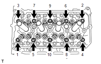
Image 25
a. Remove the cylinder head gasket from the cylinder block sub-assembly.
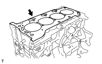
Image 26
5. INSPECT CYLINDER HEAD FOR FLATNESS
Refer to PROCEDURE - Step 1
6. INSPECT CYLINDER HEAD SET BOLT
Refer to PROCEDURE - Step 15
INSTALLATION [01/2019 - ]
CAUTION / NOTICE / HINT
HINT:
Perform "Inspection After Repair" after replacing the cylinder head sub-assembly.
Refer to INITIALIZATION [01/2019 - ]
PROCEDURE
1. INSTALL CYLINDER HEAD GASKET
a. Remove any oil from the contact surfaces.
b. Apply seal packing to the cylinder block sub-assembly as shown in the illustration.
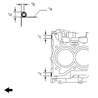
Image 27
*a
Cylinder Block Sub-assembly
*b
2.0 to 4.0 mm (0.0787 to 0.157 in.)
*c
10 to 15 mm (0.394 to 0.591 in.)
*d
Diameter 4.0 mm (0.157 in.)

Image 28
Front of Engine
Seal Packing
Toyota Genuine Seal Packing Black, Three Bond 1207B or equivalent
NOTE:
Install the cylinder head gasket within 3 minutes and tighten the cylinder head set bolts within 15 minutes of applying
packing.
c. Place a new cylinder head gasket on the cylinder block sub-assembly as shown in the illustration.
*a
Lot No.

Image 29
Front of Engine
NOTE:
Make sure to install the cylinder head gasket in the correct direction.
d. Apply seal packing to the cylinder head gasket as shown in the illustration.
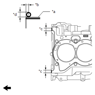
Image 30

Image 31
Front of Engine
Seal Packing
Toyota Genuine Seal Packing Black, Three Bond 1207B or equivalent
2. INSTALL CYLINDER HEAD SUB-ASSEMBLY
HINT:
The cylinder head set bolts are tightened in 3 progressive steps.
a. Clean the cylinder block sub-assembly and cylinder head sub-assembly with solvent.
b. Place the cylinder head sub-assembly on the cylinder block sub-assembly.
NOTE:
Remove any oil from the contact surface of the cylinder head sub-assembly.
Place the cylinder head sub-assembly on the cylinder block sub-assembly gently in order not to damage the gas
bottom of the cylinder head sub-assembly.
c. Install the 10 cylinder head set plate washers to the 10 cylinder head set bolts.
d. Apply a light coat of engine oil to the threads and under the heads of the cylinder head set bolts.
e. Step 1:
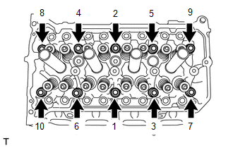
Image 32
Fig. 7: Cylinder Head Sub-Assembly Tightening Sequence
Courtesy of В© TOYOTA, LICENSE AGREEMENT TMS1002
1. Using a 10 mm bi-hexagon socket wrench, install and uniformly tighten the 10 cylinder head set bolts in several steps in the order shown in the illustr
Torque: 49 N*m (500 kgf*cm, 36 ft.*lbf)
NOTE:
Do not drop the cylinder head set plate washers for the cylinder head set bolts into the cylinder head sub-assem
f. Step 2:
*a
Paint Mark

Image 33
Front of Engine
1. Mark each cylinder head set bolt head with paint as shown in the illustration.
2. Tighten the cylinder head set bolts 90В° in the order shown in step 1.
g. Step 3:
1. Tighten the cylinder head set bolts another 45В° in the order shown in step 1.
h. Check that the paint marks are now at a 135В° angle.
NOTE:
Do not add engine oil for at least 2 hours after installing the cylinder head sub-assembly.
i. After tightening the cylinder head set bolts, wipe off any seal packing that seeped out from the contact surfaces between the cylinder head sub-assembly and
block sub-assembly.
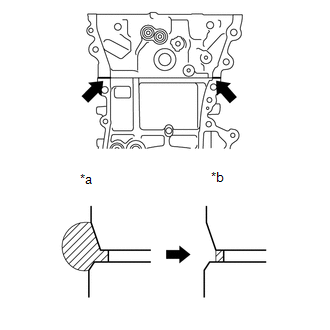
Image 34
*a
Before Wiping Off
*b
After Wiping Off
NOTE:
Be sure to wipe off the seal packing from inside to outside, parallel to the joint line.
Be sure to avoid clogging the bolt holes when wiping off the seal packing.
3. INSTALL NO. 1 WATER BY-PASS PIPE
Refer to PROCEDURE - Step 12 [01/2019 - 03/2019] , or refer to PROCEDURE - Step 12 [03/2019 - ]
4. INSTALL CAMSHAFT HOUSING SUB-ASSEMBLY
Refer to INSTALLATION [01/2019 - ]
FRONT CRANKSHAFT OIL SEAL
COMPONENTS [01/2019 - 03/2019]
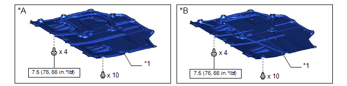
Image 35
Fig. 8: Front Crankshaft Oil Seal Replacement Components With Torque Specifications (1 Of 3) [01/2019 - 03/2019]
Courtesy of В© TOYOTA, LICENSE AGREEMENT TMS1002
*A
Type A
*B
Type B
*1
NO. 1 ENGINE UNDER COVER
ASSEMBLY
-
-

Image 36
N*m (kgf*cm, ft.*lbf): Specified torque
-
-
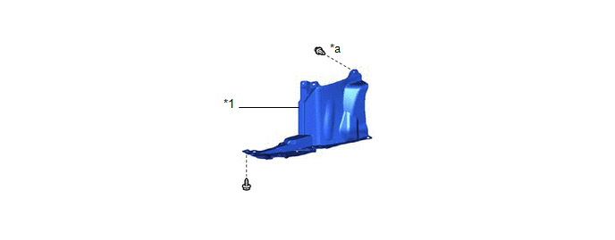
Image 37
Fig. 9: Front Crankshaft Oil Seal Replacement Components (2 Of 3) [01/2019 - 03/2019]
Courtesy of В© TOYOTA, LICENSE AGREEMENT TMS1002
*1
REAR ENGINE UNDER COVER RH
-
-
*a
Type A: x 4
Type B: x 5
-
-
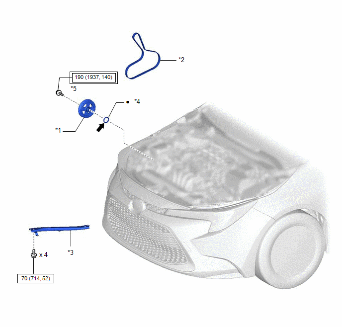
Image 38
Fig. 10: Front Crankshaft Oil Seal Replacement Components With Torque Specifications (3 Of 3) [01/2019 - 03/2019]
Courtesy of В© TOYOTA, LICENSE AGREEMENT TMS1002

Image 39
Tightening torque for
"Major areas involving
basic vehicle performance
such as
moving/turning/stopping":
N*m (kgf*cm, ft.*lbf)

Image 40
N*m
(kgf*
ft.*lb
Spec
torqu
•
Non-reusable part

Image 41
MP g
COMPONENTS [03/2019 - ]
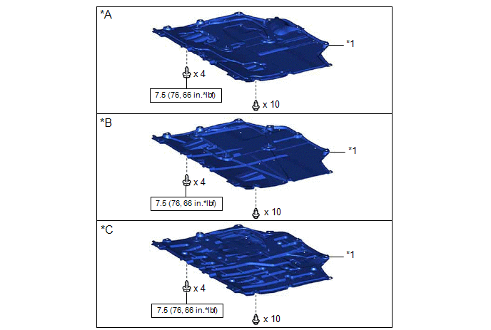
Image 42
Fig. 11: Front Crankshaft Oil Seal Replacement Components With Torque Specifications (1 Of 3) [03/2019 - ]
Courtesy of В© TOYOTA, LICENSE AGREEMENT TMS1002

Image 43
N*m (kgf*cm, ft.*lbf): Specified torque
-
-
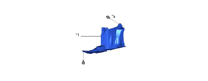
Image 44
Fig. 12: Front Crankshaft Oil Seal Replacement Components (2 Of 3) [03/2019 - ]
Courtesy of В© TOYOTA, LICENSE AGREEMENT TMS1002
*1
REAR ENGINE UNDER COVER RH
-
-
*a
Type A: x 4
Type B: x 5
-
-
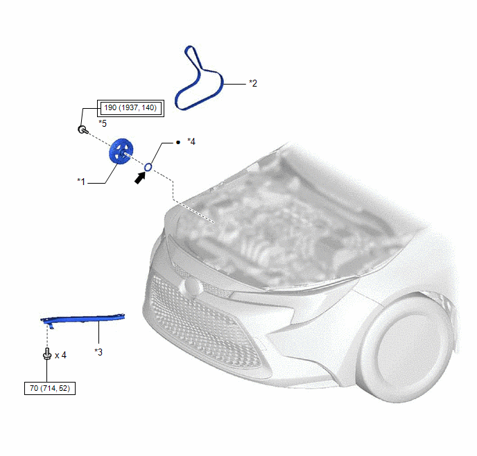
Image 45
Fig. 13: Front Crankshaft Oil Seal Replacement Components With Torque Specifications (3 Of 3) [03/2019 - ]
Courtesy of В© TOYOTA, LICENSE AGREEMENT TMS1002

Image 46
Tightening torque for
"Major areas involving
basic vehicle performance
such as
moving/turning/stopping":
N*m (kgf*cm, ft.*lbf)

Image 47
N*m
(kgf*
ft.*lb
Spec
torqu
•
Non-reusable part

Image 48
MP g
REMOVAL [01/2019 - ]
PROCEDURE
1. REMOVE FRONT WHEEL RH
Refer to REMOVAL [01/2019 - 03/2019] , or refer to REMOVAL [03/2019 - ][01/2019 - 03/2019][01/2019 - 03/2019][01/2019 - 03/2019][01/2019 - 03/2019]
2. REMOVE NO. 1 ENGINE UNDER COVER ASSEMBLY
See step 7 [01/2019 - 03/2019], or see step 7 [03/2019 - ]
3. REMOVE REAR ENGINE UNDER COVER RH
See step 9 [01/2019 - 03/2019], or see step 9 [03/2019 - ]
4. REMOVE REAR SIDE RAIL REINFORCEMENT SUB-ASSEMBLY RH
Refer to PROCEDURE - Step 11
5. REMOVE V-RIBBED BELT
Refer to PROCEDURE - Step 2
6. REMOVE CRANKSHAFT PULLEY
a. Using SST to hold the crankshaft pulley, loosen the crankshaft pulley set bolt. Further loosen the crankshaft pulley set bolt until 2 or 3 threads remain screw
crankshaft.

Image 49
*a
Hold
*b
Turn
SST: 09213-54015
91551-00850
SST: 09330-00021
b. Using SST and the crankshaft pulley set bolt, remove the crankshaft pulley and crankshaft pulley set bolt.
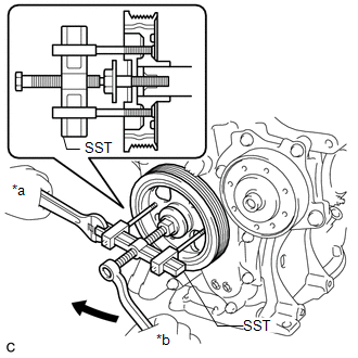
Image 50
*a
Hold
*b
Turn
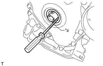
Image 51
*a
Protective Tape
NOTE:
After removal, check the crankshaft for damage. If it is damaged, smooth the surface with 400-grit sandpaper.
INSTALLATION [01/2019 - ]
PROCEDURE
1. INSTALL TIMING CHAIN COVER OIL SEAL
a. Apply MP grease to the lip of a new timing chain cover oil seal.
NOTE:
Keep the lip free from foreign matter.
b. Using SST and a hammer, tap in the timing chain cover oil seal until its surface is flush with the timing chain cover sub-assembly edge.
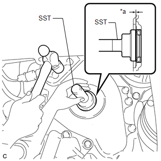
Image 52
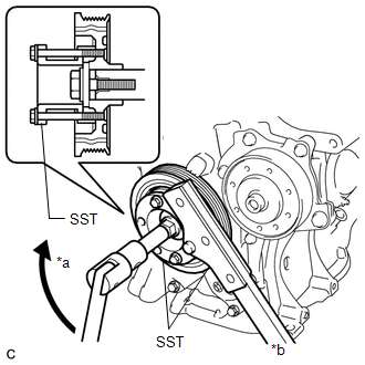
Image 53
*a
Turn
*b
Hold
SST: 09213-54015
91551-00850
SST: 09330-00021
Torque: 190 N*m (1937 kgf*cm, 140 ft.*lbf)
3. INSTALL V-RIBBED BELT
Refer to PROCEDURE - Step 1
4. INSPECT V-RIBBED BELT
See step 1
5. INSTALL REAR SIDE RAIL REINFORCEMENT SUB-ASSEMBLY RH
Refer to PROCEDURE - Step 19
6. INSPECT FOR OIL LEAK
Refer to PROCEDURE - Step 6 [01/2019 - 03/2019] , or refer to PROCEDURE - Step 6 [03/2019 - ][03/2019 - ][03/2019 - ][03/2019 - ][03/2019 - ]
7. INSTALL REAR ENGINE UNDER COVER RH
See step 73 [01/2019 - 03/2019], or see step 73 [03/2019 - ]
8. INSTALL NO. 1 ENGINE UNDER COVER ASSEMBLY
See step 74 [01/2019 - 03/2019], or see step 74 [03/2019 - ]
9. INSTALL FRONT WHEEL RH
Refer to INSTALLATION [01/2019 - 03/2019] , or refer to INSTALLATION [03/2019 - ]
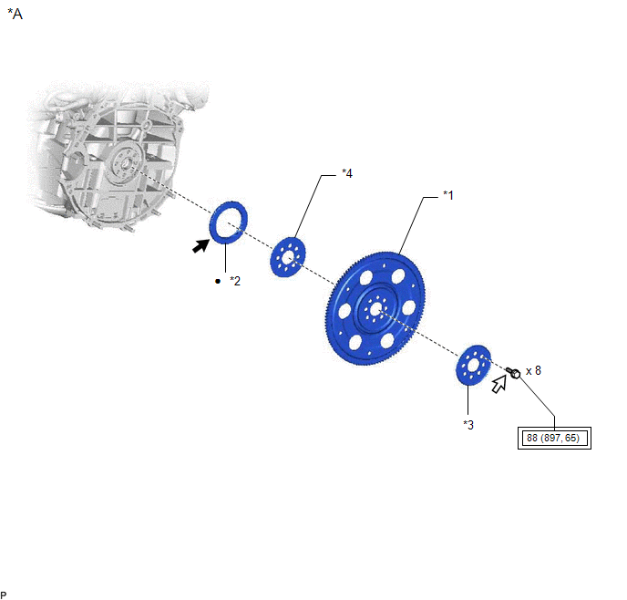
Image 54
Fig. 14: Rear Crankshaft Oil Seal Replacement Components With Torque Specifications (1 Of 2)
Courtesy of В© TOYOTA, LICENSE AGREEMENT TMS1002
*A
for CVT
-
*1
DRIVE PLATE AND
RING GEAR SUB-
ASSEMBLY
*2
REA
ENG
OIL
SEA
*3
REAR DRIVE PLATE
SPACER
*4
FRO
DRIV
PLAT
SPAC

Image 55
Tightening torque for
"Major areas involving
basic vehicle performance
such as
moving/turning/stopping":
N*m (kgf*cm, ft.*lbf)
•
Non-
reusa
part

Image 56
MP grease

Image 57
Adhe
1324
*
Precoated part
-
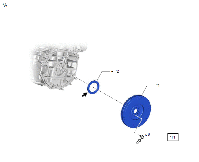
Image 58
Fig. 15: Rear Crankshaft Oil Seal Replacement Components With Torque Specifications (2 Of 2)
Courtesy of В© TOYOTA, LICENSE AGREEMENT TMS1002
*A
for Manual
Transaxle
-
-
*1
FLYWHEEL SUB-
ASSEMBLY
*2
REAR ENG
OIL SEAL

Image 59
N*m (kgf*cm,
ft.*lbf): Specified
torque
•
Non-reusab
part

Image 60
MP grease

Image 61
Adhesive 1
*
Precoated part
-
-
*T1
1st: 49 (500, 36)
2nd: Turn 90В°
-
-
REMOVAL [01/2019 - 03/2019]
CAUTION / NOTICE / HINT
The necessary procedures (adjustment, calibration, initialization, or registration) that must be performed after parts are removed and installed, or replaced during rear cra
seal removal/installation are shown below.
NECESSARY PROCEDURES AFTER PARTS REMOVED/INSTALLED/REPLACED
Replaced Part or Performed Procedure
Necessary Procedure
Effect/Inoperative Function when
Necessary Procedure not Performed
Link
Battery terminal is disconnected/reconnected
Perform steering sensor zero point calibration
Lane Control System
Refer to INITIALIZAT
[06/2018 - ]
Pre-collision System
Lighting System (w/ AFS) (EXT)
Replacement of ECM
Vehicle Identification Number (VIN)
registration
MIL comes on
Refer to REGISTRATI
[01/2019 - ]
ECU communication ID registration
(Immobiliser system)
Engine start function
Refer to REGISTRATI
[01/2019 - 09/2019]
1. Reset memory
2. Deceleration sensor zero point
calibration
3. CVT oil pressure calibration
Large shift shock
Deterioration of fuel efficiency
Refer to INITIALIZAT
[01/2019 - ]
Replacement of ECM*1
Code registration (Smart Key System (for
Gasoline Model, Start Function))
Wireless Door Lock Control System
(for Gasoline Model with Smart Key
System)
Smart Key System (for Gasoline
Model, Entry Function)
Smart Key System (for Gasoline
Model, Start Function)
Steering lock function
Refer to REGISTRATI
[01/2019 - 09/2019]
Replacement of ECM*2
Code registration (Immobiliser system)
Engine start
Refer to REGISTRATI
[01/2019 - 09/2019]
Replacement of engine assembly
Gas leak from exhaust system is repaired
Inspection After Repair
Poor idle, etc.
Engine start function, etc.
Refer to INITIALIZAT
[01/2019 - ]
Suspension, tires, etc.
(The vehicle height changes because of
suspension or tire replacement)
Perform headlight ECU sub-assembly LH
initialization
Lighting system (w/ AFS) (EXT)
Refer to INITIALIZAT
[06/2018 - ]
Front wheel alignment adjustment
1. Perform "Reset Memory".
2. Perform acceleration sensor zero point
calibration and store system
information memorization.
VSC is disabled or malfunctions
DTCs are output
Slip indicator light illuminates
ABS warning light illuminates
w/ Electric Parking Bra
System: Refer to UTILI
[06/2018 - ]
w/o Electric Parking Br
System: Refer to UTILI
[01/2019 - 03/2019]
CVT fluid
ATF thermal degradation estimate reset
The value of the Data List item "ATF
Thermal Degradation Estimate" is not
estimated correctly
Refer to INITIALIZAT
[01/2019 - ] for K313
1. REMOVE CONTINUOUSLY VARIABLE TRANSAXLE ASSEMBLY (for CVT)
Refer to REMOVAL [01/2019 - 03/2019]
2. REMOVE CLUTCH DISC ASSEMBLY (for Manual Transaxle)
Refer to REMOVAL [01/2019 - 03/2019]
3. REMOVE DRIVE PLATE AND RING GEAR SUB-ASSEMBLY (for CVT)
a. Using height adjustment attachments and plate lift attachments, place the engine assembly on a flat level surface.
NOTE:
Using height adjustment attachments and plate lift attachments, place the engine assembly horizontally.
To prevent the No. 2 oil pan sub-assembly from deforming, do not place any attachments under the No. 2 oil pan
assembly of the engine assembly.
Using an engine sling device and engine lift, secure the engine assembly before servicing.
b. Using SST, hold the crankshaft pulley.
SST: 09213-54015
91551-00850
SST: 09330-00021
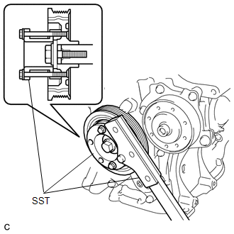
Image 62
c. Remove the 8 bolts, rear drive plate spacer, drive plate and ring gear sub-assembly and front drive plate spacer from the crankshaft.
4. REMOVE FLYWHEEL SUB-ASSEMBLY (for Manual Transaxle)
a. Using height adjustable attachments and plate lift attachments, place the engine assembly on a flat, level surface.
NOTE:
Using height adjustment attachments and plate lift attachments, place the engine assembly horizontally.
To prevent the No. 2 oil pan sub-assembly from deforming, do not place any attachments under the No. 2 oil pan
assembly of the engine assembly.
Using an engine sling device and engine lift, secure the engine assembly before servicing.
b. Using SST, hold the crankshaft pulley.
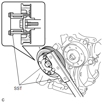
Image 63
SST: 09213-54015
91551-00850
SST: 09330-00021
c. Remove the 8 bolts and the flywheel sub-assembly from the crankshaft.
5. REMOVE REAR ENGINE OIL SEAL
a. Using a knife, cut through the lip of the rear engine oil seal.
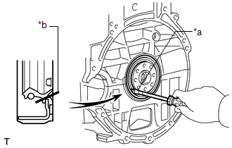
Image 64
*a
Protective Tape
*b
Cut Position
b. Using a screwdriver with its tip wrapped with protective tape, pry out the rear engine oil seal.
NOTE:
Be careful not to damage the crankshaft.
REMOVAL [03/2019 - ]
CAUTION / NOTICE / HINT
The necessary procedures (adjustment, calibration, initialization, or registration) that must be performed after parts are removed and installed, or replaced during rear cr
seal removal/installation are shown below.
NECESSARY PROCEDURES AFTER PARTS REMOVED/INSTALLED/REPLACED
Replaced Part or Performed Procedure
Necessary Procedure
Effect/Inoperative Function when
Necessary Procedure not Performed
Link
Battery terminal is disconnected/reconnected
Perform steering sensor zero point calibration
Lane Control System
Refer to INITIALIZAT
[06/2018 - ]
Pre-collision System
Lighting System (w/ AFS) (EXT)
Replacement of ECM
Vehicle Identification Number (VIN)
registration
MIL comes on
Refer to REGISTRATI
[01/2019 - ]
ECU communication ID registration
(Immobiliser system)
Engine start function
| Refer to | REGISTRATI |
|---|---|
| [01/2019 - 09/2019] | , or |
| to | REGISTRATION [09 |
- 04/2020] , or refer t
REGISTRATION [04/20
1. Reset memory
2. Deceleration sensor zero point
calibration
3. CVT oil pressure calibration
Large shift shock
Deterioration of fuel efficiency
Refer to INITIALIZAT
[01/2019 - ]
Replacement of engine assembly
Gas leak from exhaust system is repaired
Inspection After Repair
Poor idle, etc.
Engine start function, etc.
Refer to INITIALIZAT
[01/2019 - ]
Suspension, tires, etc.
(The vehicle height changes because of
suspension or tire replacement)
Perform headlight ECU sub-assembly LH
initialization
Lighting system (w/ AFS) (EXT)
Refer to INITIALIZAT
[06/2018 - ]
Front wheel alignment adjustment
1. Perform "Reset Memory".
2. Perform acceleration sensor zero point
calibration and store system
information memorization.
VSC is disabled or malfunctions
DTCs are output
Slip indicator light illuminates
ABS warning light illuminates
w/ Electric Parking Bra
System: Refer to UTILI
[06/2018 - ]
w/o Electric Parking Br
System: Refer to UTILI
[03/2019 - ]
CVT fluid
ATF thermal degradation estimate reset
The value of the Data List item "ATF
Thermal Degradation Estimate" is not
estimated correctly
Refer to INITIALIZAT
[01/2019 - ] for K313
*1: w/ Smart Key System
*2: w/o Smart Key System
NOTE:
After the ignition switch is turned off, the radio and display receiver assembly records various types of memory and settings. As
after turning the ignition switch off, make sure to wait at least 85 seconds before disconnecting the cable from the negative (-) b
terminal. (for Navigation System and Audio and Visual System (for Gasoline Model))
PROCEDURE
1. REMOVE CONTINUOUSLY VARIABLE TRANSAXLE ASSEMBLY (for CVT)
Refer to REMOVAL [03/2019 - ]
2. REMOVE CLUTCH DISC ASSEMBLY (for Manual Transaxle)
Refer to REMOVAL [03/2019 - ]
3. REMOVE DRIVE PLATE AND RING GEAR SUB-ASSEMBLY (for CVT)
a. Using height adjustment attachments and plate lift attachments, place the engine assembly on a flat level surface.
NOTE:
Using height adjustment attachments and plate lift attachments, place the engine assembly horizontally.
To prevent the No. 2 oil pan sub-assembly from deforming, do not place any attachments under the No. 2 oil pan
assembly of the engine assembly.
Using an engine sling device and engine lift, secure the engine assembly before servicing.
b. Using SST, hold the crankshaft pulley.
SST: 09213-54015
91551-00850
SST: 09330-00021
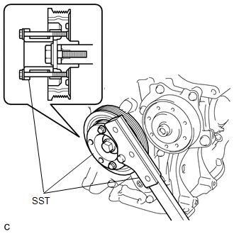
Image 65
c. Remove the 8 bolts, rear drive plate spacer, drive plate and ring gear sub-assembly and front drive plate spacer from the crankshaft.
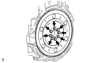
Image 66
4. REMOVE FLYWHEEL SUB-ASSEMBLY (for Manual Transaxle)
a. Using height adjustable attachments and plate lift attachments, place the engine assembly on a flat, level surface.
NOTE:
Using height adjustment attachments and plate lift attachments, place the engine assembly horizontally.
To prevent the No. 2 oil pan sub-assembly from deforming, do not place any attachments under the No. 2 oil pan
assembly of the engine assembly.
Using an engine sling device and engine lift, secure the engine assembly before servicing.
b. Using SST, hold the crankshaft pulley.
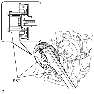
Image 67
SST: 09213-54015
91551-00850
SST: 09330-00021
c. Remove the 8 bolts and the flywheel sub-assembly from the crankshaft.
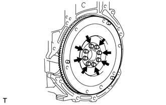
Image 68
5. REMOVE REAR ENGINE OIL SEAL
a. Using a knife, cut through the lip of the rear engine oil seal.
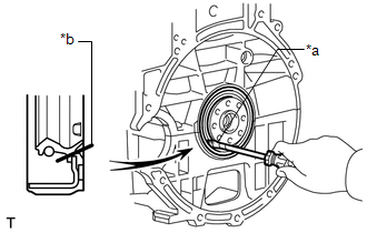
Image 69
1. INSTALL REAR ENGINE OIL SEAL
a. Using height adjustment attachments and plate lift attachments, place the engine assembly on a flat, level surface.
NOTE:
Using height adjustment attachments and plate lift attachments, place the engine assembly horizontally.
To prevent the No. 2 oil pan sub-assembly from deforming, do not place any attachments under the No. 2 oil pan
assembly of the engine assembly.
Using an engine sling device and engine lift, secure the engine assembly before servicing.
b. Apply MP grease to the lip of a new rear engine oil seal.
NOTE:
Keep the lip free from foreign matter.
c. Using SST and a hammer, tap in the rear engine oil seal until its surface is flush with the rear engine oil seal retainer edge.
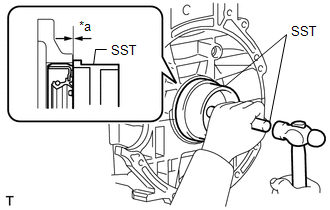
Image 70
*a
Tap in Depth
SST: 09223-15030
SST: 09950-70010
09951-07100
Timing Chain Oil Seal Tap in Depth
-1.0 to 1.0 mm (-0.0394 to 0.0394 in.)
NOTE:
Keep the lip free from foreign matter.
Do not tap in the rear engine oil seal at an angle.
2. INSTALL FLYWHEEL SUB-ASSEMBLY (for Manual Transaxle)
a. Using SST, hold the crankshaft pulley.
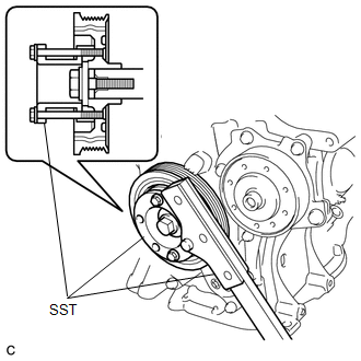
Image 71
SST: 09213-54015
91551-00850
SST: 09330-00021
b. Apply adhesive to the 2 or 3 threads at the tip of each of the 8 bolts.
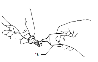
Image 72
*a
Adhesive
Adhesive
Toyota Genuine Adhesive 1324, Three Bond 1324 or equivalent
c. Using several steps, uniformly install and tighten the 8 bolts in the sequence shown in the illustration.
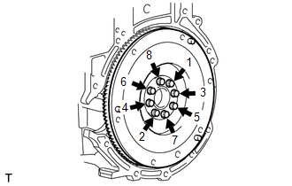
Image 73
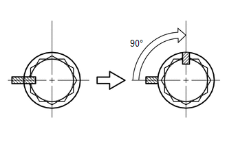
Image 74

Image 75
Paint Mark
e. Retighten the 8 bolts 90В° in the same sequence.
f. Check that the paint marks are now at a 90В° angle to the front.
g. Check that the crankshaft turns smoothly.
3. INSTALL DRIVE PLATE AND RING GEAR SUB-ASSEMBLY (for CVT)
a. Using SST, hold the crankshaft pulley.
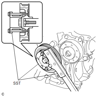
Image 76
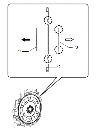
Image 77
*1
Front Drive Plate Spacer (Reversible)
*2
Drive Plate and Ring Gear Sub-assembly
*3
Rear Drive Plate Spacer

Image 78
Engine Side
d. Apply adhesive to 2 or 3 threads at the end of each of the 8 bolts.
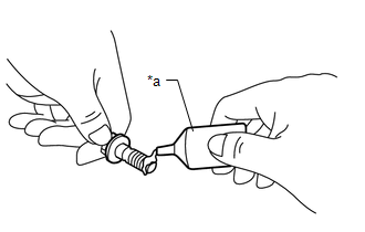
Image 79
*a
Adhesive
Adhesive
Toyota Genuine Adhesive 1324, Three Bond 1324 or equivalent
e. Install and uniformly tighten the 8 bolts in several steps in the sequence shown in the illustration.
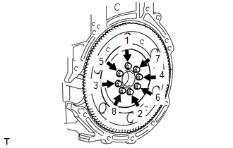
Image 80
Fig. 17: Flywheel Bolt Tightening Sequence
Courtesy of В© TOYOTA, LICENSE AGREEMENT TMS1002
Torque: 88 N*m (897 kgf*cm, 65 ft.*lbf)
NOTE:
Do not start the engine for at least 1 hour after installing the drive plate and ring gear sub-assembly.
4. INSTALL CLUTCH DISC ASSEMBLY (for Manual Transaxle)
Refer to INSTALLATION [01/2019 - ]
5. INSTALL CONTINUOUSLY VARIABLE TRANSAXLE ASSEMBLY (for CVT)
Refer to INSTALLATION [01/2019 - ]
ENGINE ASSEMBLY
*A
Type A
*B
Type B
*1
NO. 1 ENGINE UNDER COVER
ASSEMBLY
-
-

Image 81
N*m (kgf*cm, ft.*lbf): Specified torque
-
-
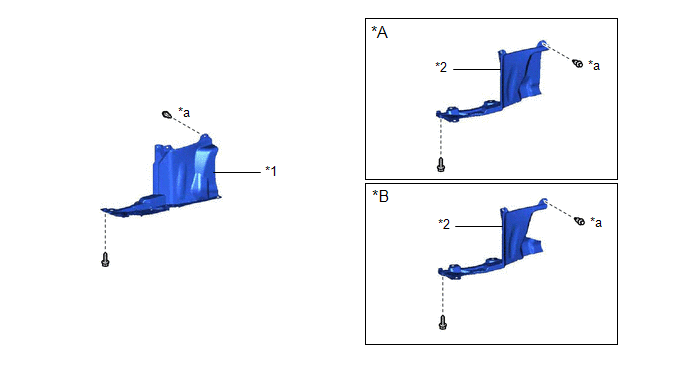
Image 82
Fig. 19: Engine Assembly Replacement Components (2 Of 8) [01/2019 - 03/2019]
Courtesy of В© TOYOTA, LICENSE AGREEMENT TMS1002
*A
for CVT
*B
for Manual Transaxle
*1
REAR ENGINE UNDER COVER RH
*2
REAR ENGINE UNDER COVER LH
*a
Type A: x 4
Type B: x 5
-
-
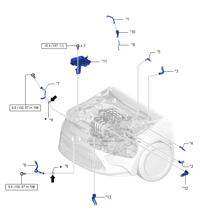
Image 83
Fig. 20: Engine Assembly Replacement Components With Torque Specifications (3 Of 8) [01/2019 - 03/2019]
Courtesy of В© TOYOTA, LICENSE AGREEMENT TMS1002
*1
FUEL TUBE SUB-ASSEMBLY
*2
OUTLET HEATER WATER HOSE
*3
INLET HEATER WATER HOSE
*4
FUEL VAPOR FEED HOSE
*5
CHECK VALVE TO CONNECTOR TUBE
HOSE
*6
SUCTION HOSE SUB-ASSEMBLY
*7
DISCHARGE HOSE SUB-ASSEMBLY
*8
FUEL PIPE
*9
O-RING
*10
NO. 1 FUEL PIPE CLAMP
*11
BATTERY CLAMP SUB-ASSEMBLY
*12
NO. 1 RADIATOR HOSE
*13
NO. 2 RADIATOR HOSE
-
-

Image 84
N*m (kgf*cm, ft.*lbf): Specified torque
•
Non-reusable part

Image 85
Compressor oil ND-OIL 12 or equivalent
-
-
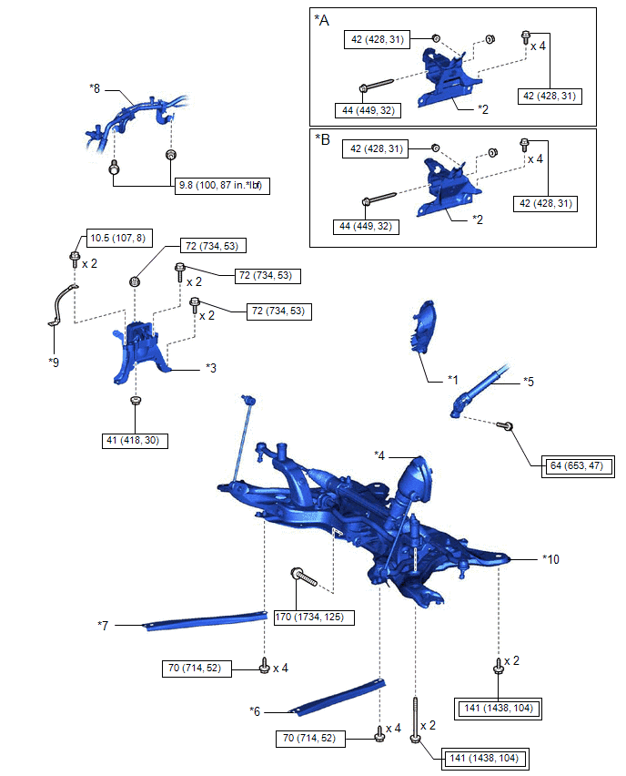
Image 86
Fig. 21: Engine Assembly Replacement Components With Torque Specifications (4 Of 8) [01/2019 - 03/2019]
Courtesy of В© TOYOTA, LICENSE AGREEMENT TMS1002
*A
for CVT
*B
for M
Trans
*1
COLUMN HOLE
COVER SILENCER
SHEET
*2
ENGI
MOU
INSU
*3
ENGINE MOUNTING
INSULATOR SUB-
ASSEMBLY RH
*4
NO. 1
COLU
COVE
ASSE

Image 87
Tightening torque for
"Major areas involving
basic vehicle performance
such as
moving/turning/stopping":
N*m (kgf*cm, ft.*lbf)

Image 88
N*m
ft.*lbf
torque
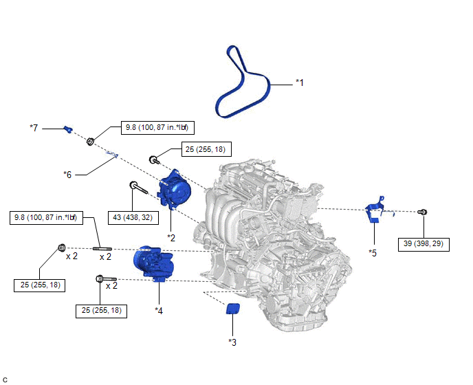
Image 89
Fig. 22: Engine Assembly Replacement Components With Torque Specifications (5 Of 8) [01/2019 - 03/2019]
Courtesy of В© TOYOTA, LICENSE AGREEMENT TMS1002
*1
V-RIBBED BELT
*2
GENERATOR ASSEMBLY
*3
FLYWHEEL HOUSING UNDER
COVER
*4
COMPRESSOR ASSEMBLY WITH
PULLEY
*5
WIRE HARNESS CLAMP BRACKET
*6
ENGINE WIRE
*7
TERMINAL CAP
-
-

Image 90
N*m (kgf*cm, ft.*lbf): Specified torque
-
-
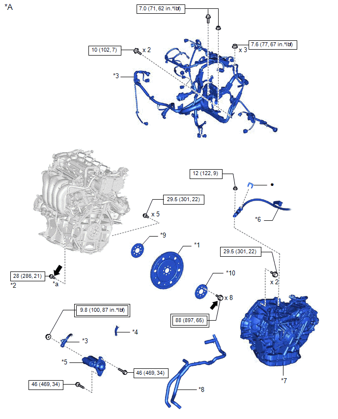
Image 91
Fig. 23: Engine Assembly Replacement Components With Torque Specifications (6 Of 8) [01/2019 - 03/2019]
Courtesy of В© TOYOTA, LICENSE AGREEMENT TMS1002
*A
for CVT
-
*1
DRIVE PLATE AND
RING GEAR SUB-
ASSEMBLY
*2
DRIV
AND
CONV
ASSE
SETT
*3
ENGINE WIRE
*4
FLYW
HOUS
COVE

Image 92
Tightening torque for
"Major areas involving
basic vehicle performance
such as
moving/turning/stopping":
N*m (kgf*cm, ft.*lbf)

Image 93
N*m
ft.*lbf
torque
•
Non-reusable part

Image 94
Adhes
*
Precoated part
-
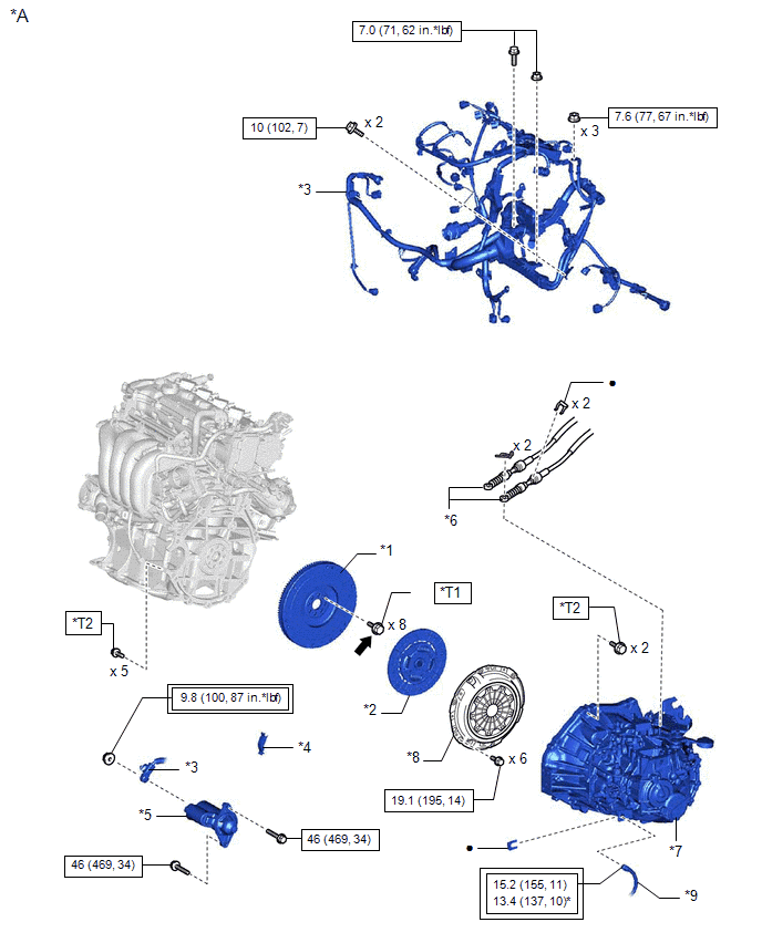
Image 95
Fig. 24: Engine Assembly Replacement Components With Torque Specifications (7 Of 8) [01/2019 - 03/2019]
Courtesy of В© TOYOTA, LICENSE AGREEMENT TMS1002
*A
for Manual Transaxle
-
*1
FLYWHEEL SUB-
ASSEMBLY
*2
CLUT
ASSE
*3
ENGINE WIRE
*4
FLYW
HOUS
COVE
*5
STARTER ASSEMBLY
*6
TRAN
CONT
CABL
ASSE
*7
MANUAL TRANSAXLE
ASSEMBLY
*8
CLUT
COVE
ASSE
*9
NO. 1 CLUTCH HOSE
-

Image 96
Tightening torque for
"Major areas involving
basic vehicle performance
such as
moving/turning/stopping":
N*m (kgf*cm, ft.*lbf)

Image 97
N*m
ft.*lbf
torque

Image 98
Adhesive 1324
*
Preco
*T1
1st: 49 (500, 36)
2nd: Turn 90В°
*T2
for Fl
37 (37
for Bo
Washe
24)
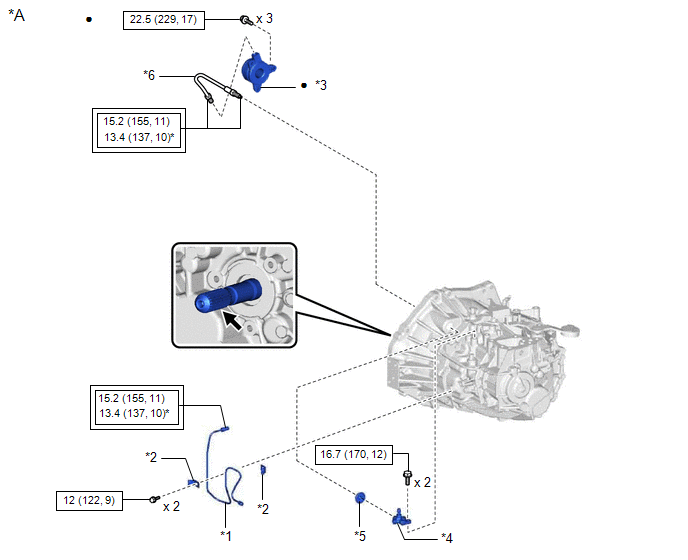
Image 99
Fig. 25: Engine Assembly Replacement Components With Torque Specifications (8 Of 8) [01/2019 - 03/2019]
Courtesy of В© TOYOTA, LICENSE AGREEMENT TMS1002
*A
for Manual Transaxle
-
*1
BLEEDER CLUTCH
RELEASE TUBE
*2
CLAM
*3
CLUTCH RELEASE
CYLINDER WITH
BEARING ASSEMBLY
*4
CLUT
RELE
BLEE
SUB-
ASSE
*5
CLUTCH TUBE BOOT
*6
CLUT
RELE
CYLI
TO
BLEE
TUBE

Image 100
Tightening torque for
"Major areas involving
basic vehicle performance
such as
moving/turning/stopping":
N*m (kgf*cm, ft.*lbf)

Image 101
N*m
(kgf*c
ft.*lbf
Speci
torque
*
For use with union nut
wrench
•
Non-
reusab

Image 102
Clutch spline grease
*
Preco
part
COMPONENTS [03/2019 - ]
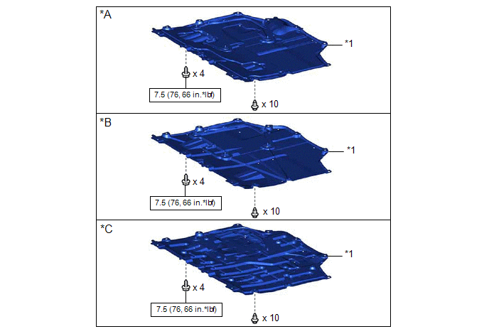
Image 103
Fig. 26: Engine Assembly Replacement Components With Torque Specifications (1 Of 8) [03/2019 - ]
Courtesy of В© TOYOTA, LICENSE AGREEMENT TMS1002
*A
Type A
*B
Type B
*C
Type C
-
-

Image 104
N*m (kgf*cm, ft.*lbf): Specified torque
-
-
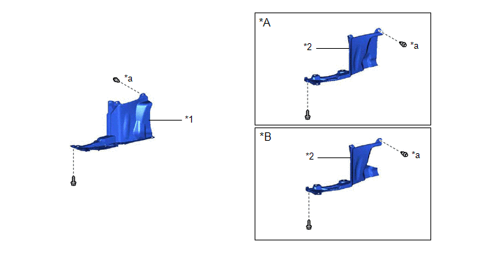
Image 105
Fig. 27: Engine Assembly Replacement Components (2 Of 8) [03/2019 - ]
Courtesy of В© TOYOTA, LICENSE AGREEMENT TMS1002
*A
for CVT
*B
for Manual Transaxle
*1
REAR ENGINE UNDER COVER RH
*2
REAR ENGINE UNDER COVER LH
*a
Type A: x 4
Type B: x 5
-
-
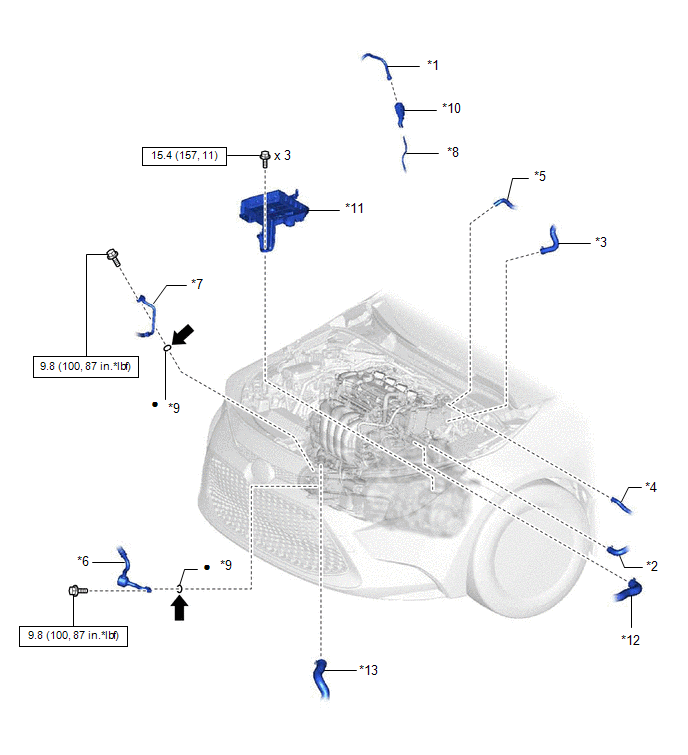
Image 106
Fig. 28: Engine Assembly Replacement Components With Torque Specifications (3 Of 8) [03/2019 - ]
Courtesy of В© TOYOTA, LICENSE AGREEMENT TMS1002
*1
FUEL TUBE SUB-ASSEMBLY
*2
OUTLET HEATER WATER HOSE
*3
INLET HEATER WATER HOSE
*4
FUEL VAPOR FEED HOSE
*5
CHECK VALVE TO CONNECTOR TUBE
HOSE
*6
SUCTION HOSE SUB-ASSEMBLY
*7
DISCHARGE HOSE SUB-ASSEMBLY
*8
FUEL PIPE
*9
O-RING
*10
NO. 1 FUEL PIPE CLAMP
*11
BATTERY CLAMP SUB-ASSEMBLY
*12
NO. 1 RADIATOR HOSE
*13
NO. 2 RADIATOR HOSE
-
-

Image 107
N*m (kgf*cm, ft.*lbf): Specified torque
•
Non-reusable part

Image 108
Compressor oil ND-OIL 12 or equivalent
-
-
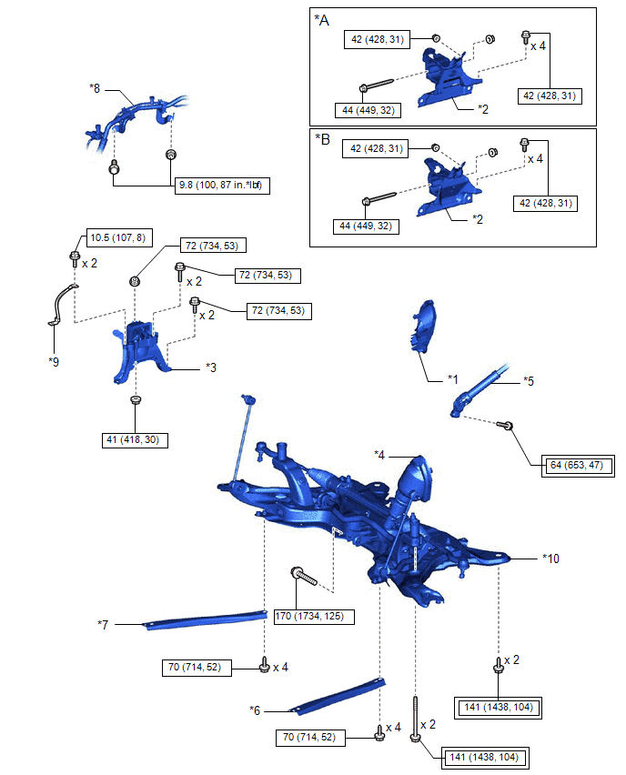
Image 109
Fig. 29: Engine Assembly Replacement Components With Torque Specifications (4 Of 8) [03/2019 - ]
Courtesy of В© TOYOTA, LICENSE AGREEMENT TMS1002
*A
for CVT
*B
for M
Trans
*1
COLUMN HOLE
COVER SILENCER
SHEET
*2
ENGI
MOU
INSU
*3
ENGINE MOUNTING
INSULATOR SUB-
ASSEMBLY RH
*4
NO. 1
COLU
COVE
ASSE

Image 110
Tightening torque for
"Major areas involving
basic vehicle performance
such as
moving/turning/stopping":
N*m (kgf*cm, ft.*lbf)

Image 111
N*m
ft.*lbf
torque
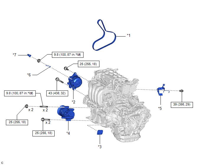
Image 112
Fig. 30: Engine Assembly Replacement Components With Torque Specifications (5 Of 8) [03/2019 - ]
Courtesy of В© TOYOTA, LICENSE AGREEMENT TMS1002
*1
V-RIBBED BELT
*2
GENERATOR ASSEMBLY
*3
FLYWHEEL HOUSING UNDER
COVER
*4
COMPRESSOR ASSEMBLY WITH
PULLEY
*5
WIRE HARNESS CLAMP BRACKET
*6
ENGINE WIRE
*7
TERMINAL CAP
-
-

Image 113
N*m (kgf*cm, ft.*lbf): Specified torque
-
-
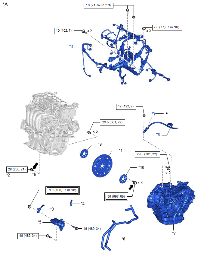
Image 114
Fig. 31: Engine Assembly Replacement Components With Torque Specifications (6 Of 8) [03/2019 - ]
Courtesy of В© TOYOTA, LICENSE AGREEMENT TMS1002
*A
for CVT
-
*1
DRIVE PLATE AND
RING GEAR SUB-
ASSEMBLY
*2
DRIV
AND
CONV
ASSE
SETT
*3
ENGINE WIRE
*4
FLYW
HOUS
COVE

Image 115
Tightening torque for
"Major areas involving
basic vehicle performance
such as
moving/turning/stopping":
N*m (kgf*cm, ft.*lbf)

Image 116
N*m
ft.*lbf
torque
•
Non-reusable part

Image 117
Adhes
*
Precoated part
-
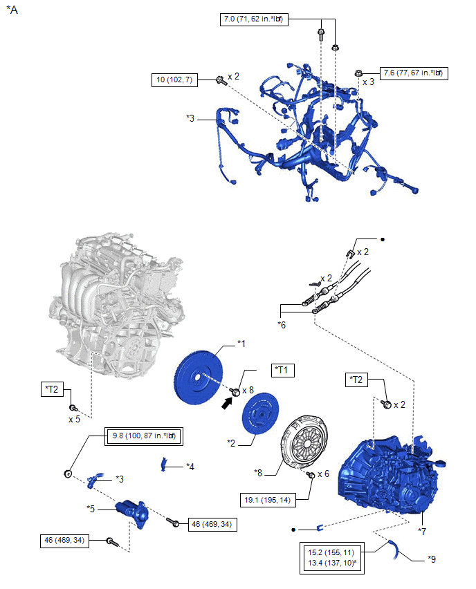
Image 118
Fig. 32: Engine Assembly Replacement Components With Torque Specifications (7 Of 8) [03/2019 - ]
Courtesy of В© TOYOTA, LICENSE AGREEMENT TMS1002
*A
for Manual Transaxle
-
*1
FLYWHEEL SUB-
ASSEMBLY
*2
CLUT
ASSE
*3
ENGINE WIRE
*4
FLYW
HOUS
COVE
*5
STARTER ASSEMBLY
*6
TRAN
CONT
CABL
ASSE
*7
MANUAL TRANSAXLE
ASSEMBLY
*8
CLUT
COVE
ASSE
*9
NO. 1 CLUTCH HOSE
-

Image 119
Tightening torque for
"Major areas involving
basic vehicle performance
such as
moving/turning/stopping":
N*m (kgf*cm, ft.*lbf)

Image 120
N*m
ft.*lbf
torque

Image 121
Adhesive 1324
*
Preco
*T1
1st: 49 (500, 36)
2nd: Turn 90В°
*T2
for Fl
37 (37
for Bo
Washe
24)
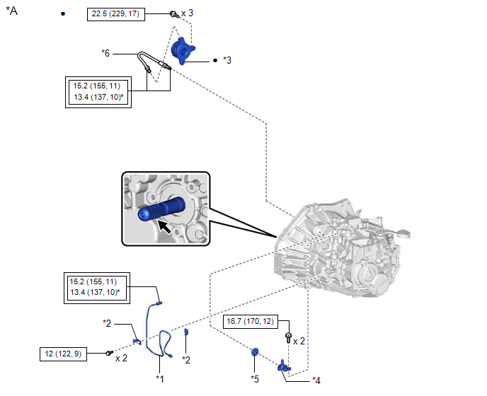
Image 122
Fig. 33: Engine Assembly Replacement Components With Torque Specifications (8 Of 8) [03/2019 - ]
Courtesy of В© TOYOTA, LICENSE AGREEMENT TMS1002
*A
for Manual Transaxle
-
*1
BLEEDER CLUTCH
RELEASE TUBE
*2
CLAM
*3
CLUTCH RELEASE
CYLINDER WITH
BEARING ASSEMBLY
*4
CLUT
RELE
BLEE
SUB-
ASSE
*5
CLUTCH TUBE BOOT
*6
CLUT
RELE
CYLI
TO
BLEE
TUBE

Image 123
Tightening torque for
"Major areas involving
basic vehicle performance
such as
moving/turning/stopping":
N*m (kgf*cm, ft.*lbf)

Image 124
N*m
(kgf*c
ft.*lbf
Speci
torque
*
For use with union nut
wrench
•
Non-
reusab

Image 125
Clutch spline grease
*
Preco
part
REMOVAL [01/2019 - 03/2019]
CAUTION / NOTICE / HINT
The necessary procedures (adjustment, calibration, initialization, or registration) that must be performed after parts are removed and installed, or replaced during engine
removal/installation are shown below.
NECESSARY PROCEDURES AFTER PARTS REMOVED/INSTALLED/REPLACED
Replaced Part or Performed Procedure
Necessary Procedure
Effect/Inoperative Function when
Necessary Procedure not Performed
Link
Battery terminal is disconnected/reconnected
Perform steering sensor zero point calibration
Lane Control System
Refer to INITIALIZAT
[06/2018 - ]
Pre-collision System
Lighting System (w/ AFS) (EXT)
Replacement of ECM
Vehicle Identification Number (VIN)
registration
MIL comes on
Refer to REGISTRATI
[01/2019 - ]
ECU communication ID registration
(Immobiliser system)
Engine start function
Refer to REGISTRATI
[01/2019 - 09/2019]
1. Reset memory
2. Deceleration sensor zero point
calibration
3. CVT oil pressure calibration
Large shift shock
Deterioration of fuel efficiency
Refer to INITIALIZAT
[01/2019 - ]
Replacement of ECM*1
Code registration (Smart Key System (for
Gasoline Model, Start Function))
Wireless Door Lock Control System
(for Gasoline Model with Smart Key
System)
Smart Key System (for Gasoline
Model, Entry Function)
Smart Key System (for Gasoline
Model, Start Function)
Steering lock function
Refer to REGISTRATI
[01/2019 - 09/2019]
Front wheel alignment adjustment
calibration and store system
information memorization.
VSC is disabled or malfunctions
DTCs are output
Slip indicator light illuminates
ABS warning light illuminates
[06/2018 - ]
w/o Electric Parking Br
System: Refer to UTILI
[01/2019 - 03/2019]
CVT fluid
ATF thermal degradation estimate reset
The value of the Data List item "ATF
Thermal Degradation Estimate" is not
estimated correctly
Refer to INITIALIZAT
[01/2019 - ] for K313
*1: w/ Smart Key System
*2: w/o Smart Key System
WARNING:
The engine assembly with transaxle is very heavy. Be sure to follow the procedure described in the repair information, or t
lifter may suddenly drop or the engine assembly with transaxle may fall off the engine lifter.
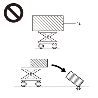
Image 126
*a
An Object Exceeding Weight Limit of Engine Lifter
To prevent burns, do not touch the engine, exhaust manifold or other high temperature components while the engine is ho
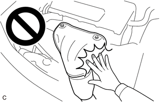
Image 127
NOTE:
After the ignition switch is turned off, the radio and display receiver assembly records various types of memory and settin
result, after turning the ignition switch off, make sure to wait at least 85 seconds before disconnecting the cable from the n
battery terminal. (for Audio and Visual System (for Gasoline Model))
After the engine switch is turned off, the radio and display receiver assembly records various types of memory and setting
result, after turning the engine switch off, make sure to wait at least 85 seconds before disconnecting the cable from the ne
battery terminal. (for Navigation System)
PROCEDURE
1. PRECAUTION
Refer to PRECAUTION [06/2018 - ]
2. RECOVER REFRIGERANT FROM REFRIGERATION SYSTEM
for HFO-1234yf(R1234yf):
Refer to PROCEDURE - Step 1
for HFC-134a(R134a):
Refer to PROCEDURE - Step 1
3. DISCHARGE FUEL SYSTEM PRESSURE
Refer to PRECAUTION [01/2019 - 03/2019]
| 4. | ALIGN FRONT WHEELS FACING STRAIGHT AHEAD |
|---|---|
| 5. | REMOVE BATTERY |
Refer to REMOVAL [01/2019 - 03/2019]
6. REMOVE FRONT WHEELS
Refer to REMOVAL [01/2019 - 03/2019]
7. REMOVE NO. 1 ENGINE UNDER COVER ASSEMBLY
a. Remove the 4 bolts.
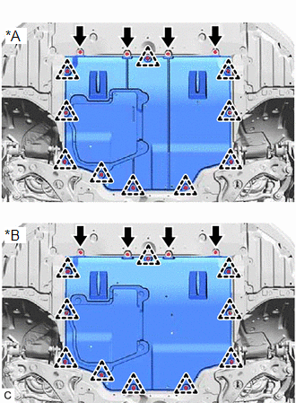
Image 128
*A
Type A
*B
Type B
b. Remove the 10 clips and No. 1 engine under cover assembly from the vehicle.
8. REMOVE REAR ENGINE UNDER COVER LH
a. Remove the 3 clips.
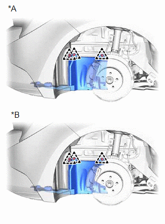
Image 129
*A
for CVT
*B
for Manual Transaxle
b. Type A:
1. Remove the screw.
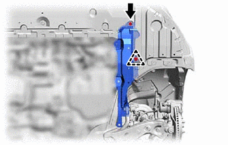
Image 130
2. Remove the clip and rear engine under cover LH from the vehicle.
c. Type B:
1. Remove the screw.
2. Remove the 2 clips and rear engine under cover LH from the vehicle.
9. REMOVE REAR ENGINE UNDER COVER RH
a. Type A:
1. Remove the screw.
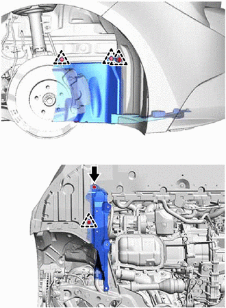
Image 131
2. Remove the 4 clips and rear engine under cover RH from the vehicle.
b. Type B:
1. Remove the screw.
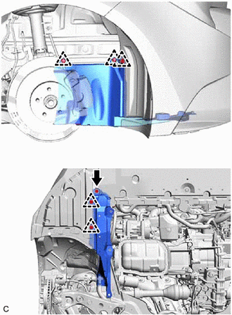
Image 132
2. Remove the 5 clips and rear engine under cover RH from the vehicle.
10. DRAIN ENGINE OIL
Refer to PROCEDURE - Step 2
11. DRAIN ENGINE COOLANT
Refer to PROCEDURE - Step 1
12. DRAIN CONTINUOUSLY VARIABLE TRANSAXLE FLUID (for CVT)
Refer to PROCEDURE - Step 3
13. DRAIN MANUAL TRANSAXLE OIL (for Manual Transaxle)
Refer to PROCEDURE - Step 3
14. REMOVE ECM
Refer to REMOVAL [01/2019 - 03/2019]
15. DISCONNECT WIRE HARNESS
a. Remove the 2 bolts to separate the engine wire from the vehicle.
b. Remove the bolt and nut to separate the engine wire from the battery clamp sub-assembly.
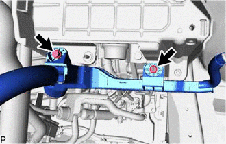
Image 133
c. Remove the 3 nuts to separate the engine wire from the positive (+) battery terminal.
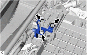
Image 134
16. REMOVE BATTERY CLAMP SUB-ASSEMBLY
a. Disengage the clamp to separate the engine wire from the battery clamp sub-assembly.
b. Remove the 3 bolts and battery clamp sub-assembly from the vehicle.
17. DISCONNECT NO. 1 RADIATOR HOSE
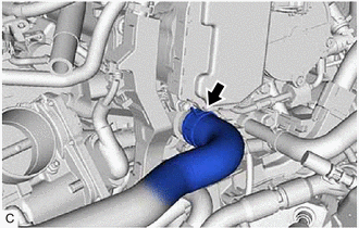
Image 135
a. Slide the clip and disconnect the No. 1 radiator hose from the cylinder head sub-assembly.
18. DISCONNECT NO. 2 RADIATOR HOSE
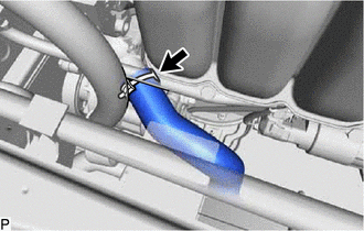
Image 136
a. Slide the clip and disconnect the No. 2 radiator hose from the water inlet.
19. DISCONNECT FLOOR SHIFT TRANSMISSION CONTROL SELECT CABLE (for CVT)
Refer to PROCEDURE - Step 13
20. DISCONNECT TRANSMISSION CONTROL CABLE ASSEMBLY (for Manual Transaxle)
a. Remove the 2 clips (A) to disconnect the transmission control cable assembly from the manual transaxle assembly.
b. Remove the 2 clips (B) to disconnect the transmission control cable assembly from the control cable bracket assembly.
21. DISCONNECT FUEL VAPOR FEED HOSE
a. Slide the clip and disconnect the fuel vapor feed hose from the purge valve (purge VSV).
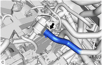
Image 137
22. DISCONNECT CHECK VALVE TO CONNECTOR TUBE HOSE
Refer to PROCEDURE - Step 2
23. DISCONNECT OUTLET HEATER WATER HOSE
a. Disengage the clamp.
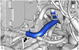
Image 138
b. Slide the clip and disconnect the outlet heater water hose from the cylinder head sub-assembly.
24. DISCONNECT INLET HEATER WATER HOSE
25. DISCONNECT FUEL TUBE SUB-ASSEMBLY
a. Disengage the claw and remove the No. 1 fuel pipe clamp.
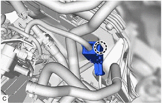
Image 139
b. Disconnect the fuel tube sub-assembly from the fuel pipe.
Refer to PRECAUTION [01/2019 - 03/2019]
26. DISCONNECT DISCHARGE HOSE SUB-ASSEMBLY
Refer to PROCEDURE - Step 5
27. DISCONNECT SUCTION HOSE SUB-ASSEMBLY
Refer to PROCEDURE - Step 4
28. SECURE STEERING WHEEL ASSEMBLY
Refer to PROCEDURE - Step 2
29. REMOVE COLUMN HOLE COVER SILENCER SHEET
Refer to PROCEDURE - Step 13
30. SEPARATE NO. 2 STEERING INTERMEDIATE SHAFT ASSEMBLY
Refer to PROCEDURE - Step 14
31. SEPARATE NO. 1 STEERING COLUMN HOLE COVER SUB-ASSEMBLY
Refer to PROCEDURE - Step 5
32. REMOVE FRONT EXHAUST PIPE ASSEMBLY (TWC: Front and Rear Catalyst)
Refer to REMOVAL [01/2019 - ]
33. REMOVE DRIVE SHAFT ASSEMBLY
Refer to REMOVAL [01/2019 - ]
35. REMOVE DRIVE PLATE AND TORQUE CONVERTER ASSEMBLY SETTING BOLT (for CVT)
Refer to PROCEDURE - Step 33
36. DISCONNECT NO. 1 CLUTCH HOSE (for Manual Transaxle)
a. Using a 10 mm union nut wrench, disconnect the bleeder clutch release tube from the No. 1 clutch hose.
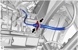
Image 140
b. Remove the clip and disconnect the No. 1 clutch hose from the clutch flexible hose bracket.
37. REMOVE REAR SIDE RAIL REINFORCEMENT SUB-ASSEMBLY LH
Refer to PROCEDURE - Step 10
38. REMOVE REAR SIDE RAIL REINFORCEMENT SUB-ASSEMBLY RH
HINT:
Use the same procedure as for the LH side.
39. REMOVE ENGINE ASSEMBLY WITH TRANSAXLE
a. Set the engine assembly with transaxle on an engine lifter.
NOTE:
Using height adjustment attachments and plate lift attachments, keep the engine assembly with transaxle and fr
suspension crossmember sub-assembly level.
Do not perform any procedures while the engine assembly is suspended because doing so may cause the engin
to drop, resulting in injury. However, the engine assembly needs to be suspended when it is installed to or remo
engine stand.
To prevent the engine assembly from unexpectedly moving, securely support the engine assembly until it is sec
engine stand.
To prevent the oil pan sub-assembly from deforming, do not place any attachments under the oil pan sub-assem
engine assembly with transaxle.
b. Remove the 2 bolts and nut and separate the engine mounting insulator sub-assembly RH from the engine mounting bracket RH.
c. Remove the bolt and nut and separate the engine mounting insulator LH from the engine mounting bracket LH.
NOTE:
While holding the nut in place, loosen the bolt.
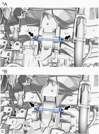
Image 141
*A
for CVT
*B
for Manual Transaxle
d. Remove the 4 bolts to separate the front suspension crossmember sub-assembly from the vehicle.
e. Operate the engine lifter and remove the engine assembly with transaxle from the vehicle.
NOTE:
Make sure that the engine assembly with transaxle is clear of all wiring and hoses.
While lowering the engine assembly with transaxle from the vehicle, do not allow it to contact the vehicle.
40. REMOVE WIRE HARNESS CLAMP BRACKET
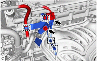
Image 142
a. Disengage the 4 clamps.
b. Disconnect the air fuel ratio sensor connector.
c. Remove the bolt and wire harness clamp bracket.
41. INSTALL ENGINE HANGERS
a. Install the No. 1 engine hanger and No. 2 engine hanger with the 2 bolts.
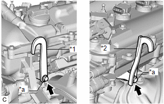
Image 143
42. REMOVE ENGINE MOUNTING INSULATOR LH
HINT:
Perform this procedure only when replacement of the engine mounting insulator LH is necessary.
a. Remove the 4 bolts, nut and engine mounting insulator LH from the vehicle.
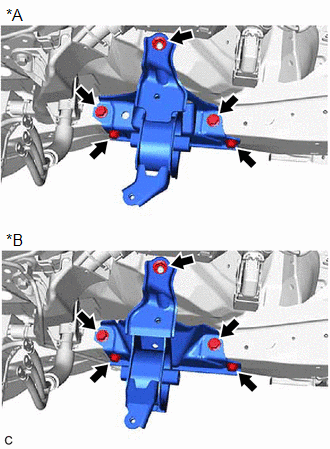
Image 144
*A
for CVT
*B
for Manual Transaxle
43. REMOVE ENGINE MOUNTING INSULATOR SUB-ASSEMBLY RH
HINT:
Perform this procedure only when replacement of the engine mounting insulator sub-assembly RH is necessary.
a. Remove the 2 bolts and No. 2 earth wire from the engine mounting insulator sub-assembly RH and vehicle.
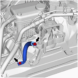
Image 145
b. Remove the bolt, nut and disconnect the air conditioner tube and accessory assembly.
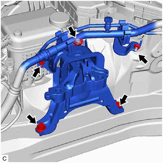
Image 146
c. Remove the 2 bolts, nut and engine mounting insulator sub-assembly RH from the vehicle.
44. REMOVE STARTER ASSEMBLY
Refer to PROCEDURE - Step 4
45. REMOVE FLYWHEEL HOUSING SIDE COVER
a. Remove the flywheel housing side cover from the cylinder block sub-assembly.
46. REMOVE ENGINE WIRE
a. Disconnect all the clamps and connectors and remove the engine wire from the engine assembly with transaxle.
47. REMOVE WATER BY-PASS HOSE ASSEMBLY (for CVT)
a. Disengage the clamp.
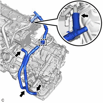
Image 147
b. Slide the 2 clips and remove the water by-pass hose assembly from the No. 3 water by-pass pipe and cylinder head sub-assembly.
c. Slide the 2 clips and remove the water by-pass hose assembly from the oil cooler.
48. REMOVE ENGINE ASSEMBLY (for CVT)
Refer to PROCEDURE - Step 42
49. REMOVE ENGINE ASSEMBLY (for Manual Transaxle)
Refer to PROCEDURE - Step 36
50. REMOVE DRIVE PLATE AND RING GEAR SUB-ASSEMBLY (for CVT)
See step 3
51. REMOVE BLEEDER CLUTCH RELEASE TUBE (for Manual Transaxle)
Refer to PROCEDURE - Step 2
52. REMOVE CLUTCH RELEASE BLEEDER SUB-ASSEMBLY (for Manual Transaxle)
57. REMOVE FLYWHEEL SUB-ASSEMBLY (for Manual Transaxle)
See step 4
58. REMOVE V-RIBBED BELT
Refer to PROCEDURE - Step 2
59. REMOVE GENERATOR ASSEMBLY
Refer to PROCEDURE - Step 3
60. REMOVE COMPRESSOR ASSEMBLY WITH PULLEY
Refer to PROCEDURE - Step 6
61. INSTALL ENGINE TO ENGINE STAND
a. Install the engine assembly to an engine stand.
62. REMOVE ENGINE HANGERS
a. Remove the 2 bolts, No. 1 engine hanger and No. 2 engine hanger.
REMOVAL [03/2019 - ]
CAUTION / NOTICE / HINT
The necessary procedures (adjustment, calibration, initialization, or registration) that must be performed after parts are removed and installed, or replaced during engine
removal/installation are shown below.
NECESSARY PROCEDURES AFTER PARTS REMOVED/INSTALLED/REPLACED
Replaced Part or Performed Procedure
Necessary Procedure
Effect/Inoperative Function when
Necessary Procedure not Performed
Link
Battery terminal is disconnected/reconnected
Perform steering sensor zero point calibration
Lane Control System
Refer to INITIALIZAT
[06/2018 - ]
Pre-collision System
Lighting System (w/ AFS) (EXT)
Replacement of ECM
Vehicle Identification Number (VIN)
registration
MIL comes on
Refer to REGISTRATI
[01/2019 - ]
ECU communication ID registration
(Immobiliser system)
Engine start function
| Refer to | REGISTRATI |
|---|---|
| [01/2019 - 09/2019] | , or |
| to | REGISTRATION [09 |
- 04/2020] , or refer t
REGISTRATION [04/20
1. Reset memory
2. Deceleration sensor zero point
calibration
3. CVT oil pressure calibration
Large shift shock
Deterioration of fuel efficiency
Refer to INITIALIZAT
[01/2019 - ]
Replacement of ECM*1
Code registration (Smart Key System (for
Gasoline Model, Start Function))
Wireless Door Lock Control System
(for Gasoline Model with Smart Key
System)
Smart Key System (for Gasoline
Model, Entry Function)
Smart Key System (for Gasoline
Model, Start Function)
Steering lock function
| Refer to | REGISTRATI |
|---|---|
| [01/2019 - 09/2019] | , or |
| to | REGISTRATION [09 |
- 04/2020] , or refer t
REGISTRATION [04/20
Replacement of ECM*2
Code registration (Immobiliser system)
Engine start
| Refer to | REGISTRATI |
|---|---|
| [01/2019 - 09/2019] | , or |
| to | REGISTRATION [09 |
- 04/2020] , or refer t
REGISTRATION [04/20
Replacement of engine assembly
Gas leak from exhaust system is repaired
Inspection After Repair
Poor idle, etc.
Engine start function, etc.
Refer to INITIALIZAT
[01/2019 - ]
Suspension, tires, etc.
(The vehicle height changes because of
suspension or tire replacement)
Perform headlight ECU sub-assembly LH
initialization
Lighting system (w/ AFS) (EXT)
Refer to INITIALIZAT
[06/2018 - ]
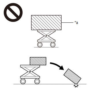
Image 148
*a
An Object Exceeding Weight Limit of Engine Lifter
To prevent burns, do not touch the engine, exhaust manifold or other high temperature components while the engine is ho
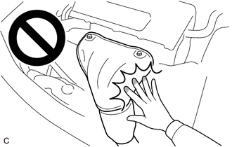
Image 149
NOTE:
After the ignition switch is turned off, the radio and display receiver assembly records various types of memory and settings. As
after turning the ignition switch off, make sure to wait at least 85 seconds before disconnecting the cable from the negative (-) b
terminal. (for Navigation System and Audio and Visual System (for Gasoline Model))
Refer to PRECAUTION [03/2019 - ]
| 4. | ALIGN FRONT WHEELS FACING STRAIGHT AHEAD |
|---|---|
| 5. | REMOVE BATTERY |
Refer to REMOVAL [03/2019 - ]
6. REMOVE FRONT WHEELS
Refer to REMOVAL [03/2019 - ]
7. REMOVE NO. 1 ENGINE UNDER COVER ASSEMBLY
a. Remove the 4 bolts.
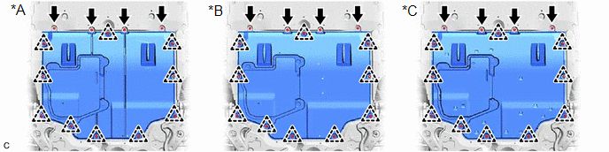
Image 150
*A
Type A
*B
Type B
*C
Type C
-
-
b. Remove the 10 clips and No. 1 engine under cover assembly from the vehicle.
8. REMOVE REAR ENGINE UNDER COVER LH
a. Remove the 3 clips.
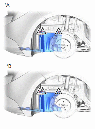
Image 151
*A
for CVT
*B
for Manual Transaxle
b. Type A:
1. Remove the screw.
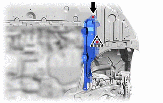
Image 152
2. Remove the clip and rear engine under cover LH from the vehicle.
c. Type B:
1. Remove the screw.
2. Remove the 2 clips and rear engine under cover LH from the vehicle.
9. REMOVE REAR ENGINE UNDER COVER RH
a. Type A:
1. Remove the screw.
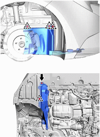
Image 153
2. Remove the 4 clips and rear engine under cover RH from the vehicle.
b. Type B:
1. Remove the screw.
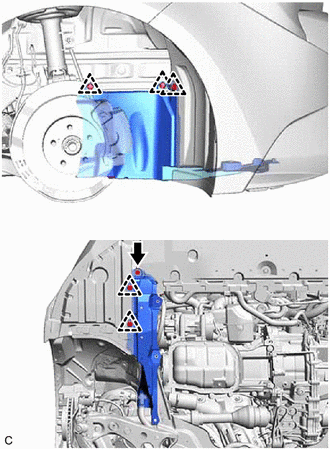
Image 154
2. Remove the 5 clips and rear engine under cover RH from the vehicle.
10. DRAIN ENGINE OIL
Refer to PROCEDURE - Step 2
11. DRAIN ENGINE COOLANT
Refer to PROCEDURE - Step 1
12. DRAIN CONTINUOUSLY VARIABLE TRANSAXLE FLUID (for CVT)
Refer to PROCEDURE - Step 3
13. DRAIN MANUAL TRANSAXLE OIL (for Manual Transaxle)
Refer to PROCEDURE - Step 3
14. REMOVE ECM
Refer to REMOVAL [03/2019 - ]
15. DISCONNECT WIRE HARNESS
a. Remove the 2 bolts to separate the engine wire from the vehicle.
b. Remove the bolt and nut to separate the engine wire from the battery clamp sub-assembly.
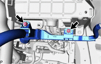
Image 155
c. Remove the 3 nuts to separate the engine wire from the positive (+) battery terminal.
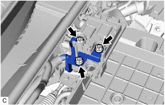
Image 156
16. REMOVE BATTERY CLAMP SUB-ASSEMBLY
a. Disengage the clamp to separate the engine wire from the battery clamp sub-assembly.
b. Remove the 3 bolts and battery clamp sub-assembly from the vehicle.
17. DISCONNECT NO. 1 RADIATOR HOSE
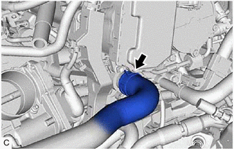
Image 157
a. Slide the clip and disconnect the No. 1 radiator hose from the cylinder head sub-assembly.
18. DISCONNECT NO. 2 RADIATOR HOSE
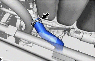
Image 158
a. Slide the clip and disconnect the No. 2 radiator hose from the water inlet.
19. DISCONNECT FLOOR SHIFT TRANSMISSION CONTROL SELECT CABLE (for CVT)
Refer to REMOVAL [03/2019 - ]
20. DISCONNECT TRANSMISSION CONTROL CABLE ASSEMBLY (for Manual Transaxle)
a. Remove the 2 clips (A) to disconnect the transmission control cable assembly from the manual transaxle assembly.
b. Remove the 2 clips (B) to disconnect the transmission control cable assembly from the control cable bracket assembly.
21. DISCONNECT FUEL VAPOR FEED HOSE
a. Slide the clip and disconnect the fuel vapor feed hose from the purge valve (purge VSV).
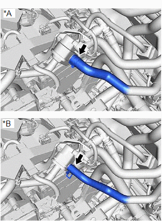
Image 159
*A
w/ Canister Pump Module
*B
w/o Canister Pump Module
22. DISCONNECT CHECK VALVE TO CONNECTOR TUBE HOSE
for TMC Made:
Refer to PROCEDURE - Step 2
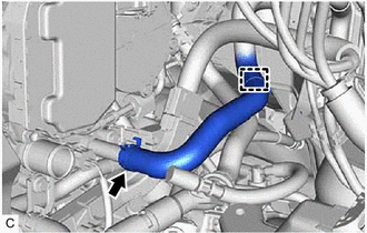
Image 160
b. Slide the clip and disconnect the outlet heater water hose from the cylinder head sub-assembly.
24. DISCONNECT INLET HEATER WATER HOSE
a. Slide the clip and disconnect the inlet heater water hose from the No. 1 water by-pass pipe.
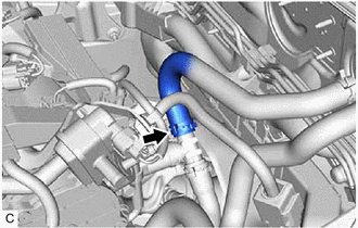
Image 161
25. DISCONNECT FUEL TUBE SUB-ASSEMBLY
a. Disengage the claw and remove the No. 1 fuel pipe clamp.
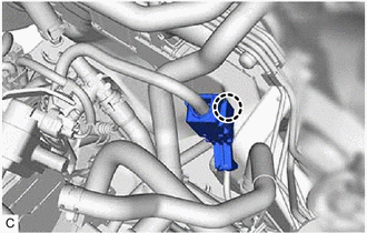
Image 162
b. Disconnect the fuel tube sub-assembly from the fuel pipe.
Refer to PRECAUTION [03/2019 - ]
Refer to PROCEDURE - Step 14 [03/2019 - 09/2019] , or refer to PROCEDURE - Step 14 [09/2019 - 04/2020] , or refer to PROCEDURE - Step 14 [04/2020
31. SEPARATE NO. 1 STEERING COLUMN HOLE COVER SUB-ASSEMBLY
Refer to PROCEDURE - Step 5
32. REMOVE FRONT EXHAUST PIPE ASSEMBLY (TWC: Front and Rear Catalyst)
Refer to REMOVAL [01/2019 - ]
33. REMOVE DRIVE SHAFT ASSEMBLY
Refer to REMOVAL [01/2019 - ]
34. REMOVE FLYWHEEL HOUSING UNDER COVER
a. Remove the flywheel housing under cover from the stiffening crankcase assembly.
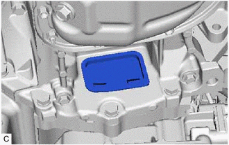
Image 163
35. REMOVE DRIVE PLATE AND TORQUE CONVERTER ASSEMBLY SETTING BOLT (for CVT)
Refer to PROCEDURE - Step 33
36. DISCONNECT NO. 1 CLUTCH HOSE (for Manual Transaxle)
a. Using a 10 mm union nut wrench, disconnect the bleeder clutch release tube from the No. 1 clutch hose.
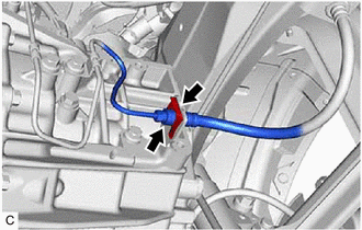
Image 164
b. Remove the clip and disconnect the No. 1 clutch hose from the clutch flexible hose bracket.
37. REMOVE REAR SIDE RAIL REINFORCEMENT SUB-ASSEMBLY LH
b. Remove the 2 bolts and nut and separate the engine mounting insulator sub-assembly RH from the engine mounting bracket RH.
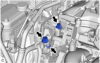
Image 165
c. Remove the bolt and nut and separate the engine mounting insulator LH from the engine mounting bracket LH.
NOTE:
While holding the nut in place, loosen the bolt.
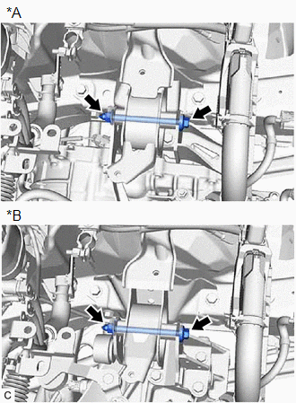
Image 166
*A
for CVT
*B
for Manual Transaxle
d. Remove the 4 bolts to separate the front suspension crossmember sub-assembly from the vehicle.
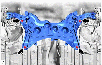
Image 167
e. Operate the engine lifter and remove the engine assembly with transaxle from the vehicle.
NOTE:
Make sure that the engine assembly with transaxle is clear of all wiring and hoses.
While lowering the engine assembly with transaxle from the vehicle, do not allow it to contact the vehicle.
40. REMOVE WIRE HARNESS CLAMP BRACKET
a. Disengage the 4 clamps.
b. Disconnect the air fuel ratio sensor connector.
c. Remove the bolt and wire harness clamp bracket.
41. INSTALL ENGINE HANGERS
a. Install the No. 1 engine hanger and No. 2 engine hanger with the 2 bolts.
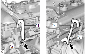
Image 168
*1
No. 1 Engine Hanger
*2
No. 2 Engine Hanger
*a
Bolt
Torque: 43 N*m (438 kgf*cm, 32 ft.*lbf)
HINT:
No. 1 Engine Hanger
12281-37070
12281-37021
No. 2 Engine Hanger
12282-37060
12282-37011
Bolt
91552-81050
90105-A0169
b. Attach an engine sling device and hang the engine assembly with transaxle with a chain block.
NOTE:
Pay attention to the angle of the sling device as the engine assembly or No. 1 engine hanger and No. 2 engine ha
be damaged or deformed if the angle is incorrect.
Do not perform any procedure while the engine assembly with transaxle is suspended because doing so may ca
engine assembly with transaxle to drop, resulting in injury. However, the engine assembly with transaxle needs
suspended when it is installed to or removed from an engine stand.
42. REMOVE ENGINE MOUNTING INSULATOR LH
HINT:
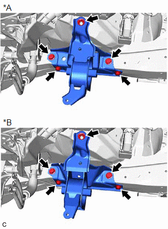
Image 169
*A
for CVT
*B
for Manual Transaxle
43. REMOVE ENGINE MOUNTING INSULATOR SUB-ASSEMBLY RH
HINT:
Perform this procedure only when replacement of the engine mounting insulator sub-assembly RH is necessary.
a. Remove the 2 bolts and No. 2 earth wire from the engine mounting insulator sub-assembly RH and vehicle.
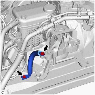
Image 170
b. Remove the bolt, nut and disconnect the air conditioner tube and accessory assembly.
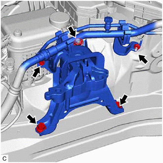
Image 171
c. Remove the 2 bolts, nut and engine mounting insulator sub-assembly RH from the vehicle.
44. REMOVE STARTER ASSEMBLY
Refer to PROCEDURE - Step 4
45. REMOVE FLYWHEEL HOUSING SIDE COVER
a. Remove the flywheel housing side cover from the cylinder block sub-assembly.
46. REMOVE ENGINE WIRE
a. Disconnect all the clamps and connectors and remove the engine wire from the engine assembly with transaxle.
47. REMOVE WATER BY-PASS HOSE ASSEMBLY (for CVT)
a. Disengage the clamp.
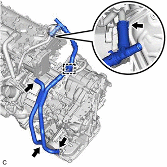
Image 172
b. Slide the 2 clips and remove the water by-pass hose assembly from the No. 3 water by-pass pipe and cylinder head sub-assembly.
c. Slide the 2 clips and remove the water by-pass hose assembly from the oil cooler.
48. REMOVE ENGINE ASSEMBLY (for CVT)
Refer to PROCEDURE - Step 42
49. REMOVE ENGINE ASSEMBLY (for Manual Transaxle)
Refer to PROCEDURE - Step 36
50. REMOVE DRIVE PLATE AND RING GEAR SUB-ASSEMBLY (for CVT)
See step 3
51. REMOVE BLEEDER CLUTCH RELEASE TUBE (for Manual Transaxle)
Refer to PROCEDURE - Step 2
52. REMOVE CLUTCH RELEASE BLEEDER SUB-ASSEMBLY (for Manual Transaxle)
57. REMOVE FLYWHEEL SUB-ASSEMBLY (for Manual Transaxle)
See step 4
58. REMOVE V-RIBBED BELT
Refer to PROCEDURE - Step 2
59. REMOVE GENERATOR ASSEMBLY
Refer to PROCEDURE - Step 3
60. REMOVE COMPRESSOR ASSEMBLY WITH PULLEY
Refer to PROCEDURE - Step 6
61. INSTALL ENGINE TO ENGINE STAND
a. Install the engine assembly to an engine stand.
62. REMOVE ENGINE HANGERS
a. Remove the 2 bolts, No. 1 engine hanger and No. 2 engine hanger.
INSTALLATION [01/2019 - 03/2019]
CAUTION / NOTICE / HINT
WARNING:
The engine assembly with transaxle is very heavy. Be sure to follow the procedure described in the repair information, or the en
may suddenly drop.
HINT:
Perform "Inspection After Repair" after replacing the engine assembly.
Refer to INITIALIZATION [01/2019 - ]
PROCEDURE
1. INSTALL ENGINE HANGERS
See step 41
2. REMOVE ENGINE FROM ENGINE STAND
a. Remove the engine assembly from the engine stand.
3. INSTALL COMPRESSOR ASSEMBLY WITH PULLEY
Refer to PROCEDURE - Step 2
4. INSTALL GENERATOR ASSEMBLY
Refer to PROCEDURE - Step 1
5. INSTALL V-RIBBED BELT
Refer to PROCEDURE - Step 1
6. INSTALL DRIVE PLATE AND RING GEAR SUB-ASSEMBLY (for CVT)
See step 3
7. INSTALL FLYWHEEL SUB-ASSEMBLY (for Manual Transaxle)
See step 2
8. INSTALL CLUTCH DISC ASSEMBLY (for Manual Transaxle)
Refer to PROCEDURE - Step 1
9. INSTALL CLUTCH COVER ASSEMBLY (for Manual Transaxle)
Refer to PROCEDURE - Step 2
10. INSPECT AND ADJUST CLUTCH COVER ASSEMBLY (for Manual Transaxle)
15. INSTALL BLEEDER CLUTCH RELEASE TUBE (for Manual Transaxle)
Refer to PROCEDURE - Step 8
16. INSTALL ENGINE ASSEMBLY (for CVT)
Refer to PROCEDURE - Step 7
17. INSTALL ENGINE ASSEMBLY (for Manual Transaxle)
Refer to PROCEDURE - Step 10
18. INSTALL WATER BY-PASS HOSE ASSEMBLY (for CVT)
a. Install the water by-pass hose assembly to the oil cooler and slide the 2 clips to secure it.
b. Install the water by-pass hose assembly to the No. 3 water by-pass pipe and cylinder head sub-assembly and slide the 2 clips to secure it.
c. Engage the clamp.
19. INSTALL ENGINE WIRE
a. Connect all the connectors and clamps, and install the engine wire to the engine assembly with transaxle.
20. INSTALL FLYWHEEL HOUSING SIDE COVER
a. Install the flywheel housing side cover to the cylinder block sub-assembly.
21. INSTALL STARTER ASSEMBLY
Refer to PROCEDURE - Step 1
22. INSTALL ENGINE MOUNTING INSULATOR SUB-ASSEMBLY RH
HINT:
Perform this procedure only when replacement of the engine mounting insulator sub-assembly RH is necessary.
a. Temporarily install the engine mounting insulator sub-assembly RH to the vehicle.
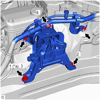
Image 173
Fig. 34: Engine Mounting Insulator Sub-Assembly RH Tightening Sequence
Courtesy of В© TOYOTA, LICENSE AGREEMENT TMS1002
*a
Temporarily Tighten
b. Install the 2 bolts and nut in the order shown in the illustration.
Torque: 72 N*m (734 kgf*cm, 53 ft.*lbf)
c. Connect the air conditioner tube and accessory assembly to the engine mounting insulator sub-assembly RH with the bolt and nut.
Torque: 9.8 N*m (100 kgf*cm, 87 in.*lbf)
d. Install the No. 2 earth wire to the engine mounting insulator sub-assembly RH and vehicle with the 2 bolts.
Torque: 10.5 N*m (107 kgf*cm, 8 ft.*lbf)
23. INSTALL ENGINE MOUNTING INSULATOR LH
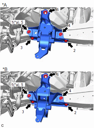
Image 174
Fig. 35: Engine Mounting Insulator LH Tightening Sequence
Courtesy of В© TOYOTA, LICENSE AGREEMENT TMS1002
*A
for CVT
*B
for Manual Transaxle
*a
Temporarily Tighten
b. Install the 4 bolts and nut in the order shown in the illustration.
Torque: 42 N*m (428 kgf*cm, 31 ft.*lbf)
24. REMOVE ENGINE HANGERS
See step 62
25. INSTALL WIRE HARNESS CLAMP BRACKET
a. Install the wire harness clamp bracket with the bolt.
Torque: 39 N*m (398 kgf*cm, 29 ft.*lbf)
b. Connect the air fuel ratio sensor connector.
c. Engage the 4 clamps.
26. INSTALL ENGINE ASSEMBLY WITH TRANSAXLE
a. Using height adjustment attachments and plate lift attachments to keep the engine assembly with transaxle and front suspension crossmember sub-assembly
engine lifter underneath the engine assembly with transaxle and front suspension crossmember sub-assembly.
NOTE:
Using height adjustment attachments and plate lift attachments, keep the engine assembly with transaxle horizo
Do not perform any procedures while the engine assembly is suspended because doing so may cause the engin
to drop, resulting in injury. However, the engine assembly needs to be suspended when it is installed to or remo
engine stand.
To prevent the oil pan sub-assembly from deforming, do not place any attachments under the oil pan sub-assem
engine assembly with transaxle.
b. Operate the engine lifter and install the engine assembly with transaxle to the vehicle.
WARNING:
Do not raise the engine assembly with transaxle more than necessary. If the engine is raised excessively, the vehicle
lifted up.
NOTE:
Make sure that the engine assembly with transaxle is clear of all wiring and hoses.
While raising the engine assembly with transaxle into the vehicle, do not allow it to contact the vehicle.
c. Connect the front suspension crossmember sub-assembly to the vehicle with the 6 bolts.
Torque: 141 N*m (1438 kgf*cm, 104 ft.*lbf)
d. Install the engine mounting insulator LH to the engine mounting bracket LH with the bolt and nut.
Torque: 44 N*m (449 kgf*cm, 32 ft.*lbf)
NOTE:
While holding the nut in place, tighten the bolt.
e. Install the engine mounting insulator sub-assembly RH to the engine mounting bracket RH with the 2 bolts and nut.
29. INSTALL DRIVE PLATE AND TORQUE CONVERTER ASSEMBLY SETTING BOLT (for CVT)
Refer to PROCEDURE - Step 15
30. INSTALL FLYWHEEL HOUSING UNDER COVER
a. Install the flywheel housing under cover to the stiffening crankcase assembly.
31. CONNECT NO. 1 CLUTCH HOSE (for Manual Transaxle)
a. Connect the No. 1 clutch hose to the clutch flexible hose bracket with a new clip.
b. Using a 10 mm union nut wrench, connect the bleeder clutch release tube to the No. 1 clutch hose.
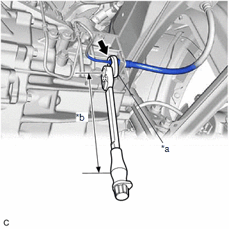
Image 175
*a
10 mm Union Nut Wrench
*b
Torque Wrench Fulcrum Length
Specified tightening torque
Torque: 15.2 N*m (155 kgf*cm, 11 ft.*lbf)
HINT:
Calculate the torque wrench reading when changing the fulcrum length of the torque wrench.
Refer to PRECAUTION [06/2018 - ]
When using a 10 mm union nut wrench (fulcrum length of 22 mm (0.866 in.)) + torque wrench (fulcrum length of 162 mm (6.38 in.)): 13.4 N*m (137
ft.*lbf)
32. INSTALL DRIVE SHAFT ASSEMBLY
Refer to INSTALLATION [01/2019 - ]
33. INSTALL FRONT EXHAUST PIPE ASSEMBLY (TWC: Front and Rear Catalyst)
Refer to INSTALLATION [01/2019 - ]
34. CONNECT NO. 1 STEERING COLUMN HOLE COVER SUB-ASSEMBLY
39. CONNECT FUEL TUBE SUB-ASSEMBLY
a. Connect the fuel tube sub-assembly to the fuel pipe.
Refer to PRECAUTION [01/2019 - 03/2019]
b. Engage the claw and install the No. 1 fuel pipe clamp.
40. CONNECT INLET HEATER WATER HOSE
a. Connect the inlet heater water hose to the No. 1 water by-pass pipe and slide the clip to secure it.
41. CONNECT OUTLET HEATER WATER HOSE
a. Connect the outlet heater water hose to the No. 3 water by-pass hose and slide the clip to secure it.
b. Engage the clamp.
42. CONNECT CHECK VALVE TO CONNECTOR TUBE HOSE
Refer to PROCEDURE - Step 2
43. CONNECT FUEL VAPOR FEED HOSE
a. Connect the fuel vapor feed hose to the purge valve (purge VSV) and slide the clip to secure it.
44. CONNECT FLOOR SHIFT TRANSMISSION CONTROL SELECT CABLE (for CVT)
Refer to PROCEDURE - Step 2
45. CONNECT TRANSMISSION CONTROL CABLE ASSEMBLY (for Manual Transaxle)
a. Install the transmission control cable assembly to the control cable bracket assembly with 2 new clips (B).
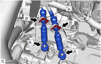
Image 176
*a
Paint Mark
NOTE:
Make sure that the paint marks on the transmission control cable assembly are aligned with the slits in the control ca
assembly before installing the clips.
b. Connect the transmission control cable assembly to the manual transaxle assembly with the 2 clips (A).
46. CONNECT NO. 2 RADIATOR HOSE
a. Connect the No. 2 radiator hose to the water inlet and slide the clip to secure it.
47. CONNECT NO. 1 RADIATOR HOSE
a. Connect the No. 1 radiator hose to the cylinder head sub-assembly and slide the clip to secure it.
48. INSTALL BATTERY CLAMP SUB-ASSEMBLY
a. Install the battery clamp sub-assembly to the vehicle with the 3 bolts.
Torque: 15.4 N*m (157 kgf*cm, 11 ft.*lbf)
b. Engage the clamp to connect the engine wire to the battery clamp sub-assembly.
49. CONNECT WIRE HARNESS
a. Connect the engine wire to the positive (+) battery terminal with the 3 nuts.
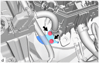
Image 177
Torque: 10 N*m (102 kgf*cm, 7 ft.*lbf)
50. INSTALL ECM
Refer to INSTALLATION [01/2019 - ]
51. INSTALL BATTERY
Refer to INSTALLATION [01/2019 - ]
52. BLEED CLUTCH LINE (for Manual Transaxle)
Refer to PROCEDURE - Step 4
53. ADD ENGINE OIL
Refer to PROCEDURE - Step 5
54. ADD ENGINE COOLANT
Refer to PROCEDURE - Step 2
55. ADD MANUAL TRANSAXLE OIL (for Manual Transaxle)
Refer to PROCEDURE - Step 4
56. ADD CONTINUOUSLY VARIABLE TRANSAXLE FLUID (for CVT)
Refer to ADJUSTMENT [01/2019 - ]
57. CHARGE AIR CONDITIONING SYSTEM WITH REFRIGERANT
for HFO-1234yf(R1234yf):
Refer to PROCEDURE - Step 2
for HFC-134a(R134a):
Refer to PROCEDURE - Step 2
58. WARM UP COMPRESSOR
for HFO-1234yf(R1234yf):
Refer to PROCEDURE - Step 4
for HFC-134a(R134a):
Refer to PROCEDURE - Step 3
59. INSPECT TRANSAXLE OIL (for Manual Transaxle)
Refer to PROCEDURE - Step 3
60. ADJUST SHIFT LEVER POSITION (for Manual Transaxle)
Refer to ADJUSTMENT [01/2019 - 03/2019]
61. INSPECT SHIFT LEVER POSITION (for CVT)
Refer to PROCEDURE - Step 2
Refer to PROCEDURE - Step 5
for HFC-134a(R134a):
Refer to PROCEDURE - Step 4
68. INSPECT FOR FUEL LEAK
Refer to PROCEDURE - Step 1
69. INSPECT FOR EXHAUST GAS LEAK
Refer to PROCEDURE - Step 7
70. CHECK ENGINE OIL LEVEL
Refer to PROCEDURE - Step 3
71. INSPECT RADIATOR RESERVE TANK ENGINE COOLANT LEVEL
Refer to PROCEDURE - Step 2
72. INSTALL REAR ENGINE UNDER COVER LH
a. Type A:
1. Install the rear engine under cover LH to the vehicle with the 4 clips.
2. Install the screw.
b. Type B:
1. Install the rear engine under cover LH to the vehicle with the 5 clips.
2. Install the screw.
73. INSTALL REAR ENGINE UNDER COVER RH
a. Type A:
1. Install the rear engine under cover RH to the vehicle with the 4 clips.
2. Install the screw.
b. Type B:
1. Install the rear engine under cover RH to the vehicle with the 5 clips.
2. Install the screw.
74. INSTALL NO. 1 ENGINE UNDER COVER ASSEMBLY
a. Install the No. 1 engine under cover assembly to the vehicle with the 10 clips.
b. Install the 4 bolts.
Torque: 7.5 N*m (76 kgf*cm, 66 in.*lbf)
75. INSTALL FRONT WHEELS
Refer to PROCEDURE - Step 1
| 76. | ALIGN FRONT WHEELS FACING STRAIGHT AHEAD |
|---|---|
| 77. | INSPECT AND ADJUST FRONT WHEEL ALIGNMENT |
Refer to ADJUSTMENT [01/2019 - 03/2019]
78. PERFORM INITIALIZATION
Refer to PROCEDURE - Step 6
79. INSPECT IGNITION TIMING
See step 8
80. INSPECT ENGINE IDLE SPEED
See step 9
81. INSPECT CO/HC
See step 11
82. CHECK SPEED SENSOR SIGNAL
1. INSTALL ENGINE HANGERS
See step 41
2. REMOVE ENGINE FROM ENGINE STAND
a. Remove the engine assembly from the engine stand.
3. INSTALL COMPRESSOR ASSEMBLY WITH PULLEY
Refer to PROCEDURE - Step 2
4. INSTALL GENERATOR ASSEMBLY
Refer to PROCEDURE - Step 1
5. INSTALL V-RIBBED BELT
Refer to PROCEDURE - Step 1
6. INSTALL DRIVE PLATE AND RING GEAR SUB-ASSEMBLY (for CVT)
See step 3
7. INSTALL FLYWHEEL SUB-ASSEMBLY (for Manual Transaxle)
See step 2
8. INSTALL CLUTCH DISC ASSEMBLY (for Manual Transaxle)
Refer to PROCEDURE - Step 1
9. INSTALL CLUTCH COVER ASSEMBLY (for Manual Transaxle)
Refer to PROCEDURE - Step 2
10. INSPECT AND ADJUST CLUTCH COVER ASSEMBLY (for Manual Transaxle)
Refer to PROCEDURE - Step 3
11. INSTALL CLUTCH RELEASE CYLINDER WITH BEARING ASSEMBLY (for Manual Transaxle)
Refer to PROCEDURE - Step 4
12. REMOVE CLUTCH RELEASE BLEEDER SUB-ASSEMBLY (for Manual Transaxle)
Refer to PROCEDURE - Step 5
13. INSPECT CLUTCH PIPE LINE (for Manual Transaxle)
Refer to PROCEDURE - Step 6
14. INSTALL CLUTCH RELEASE BLEEDER SUB-ASSEMBLY (for Manual Transaxle)
Refer to PROCEDURE - Step 7
15. INSTALL BLEEDER CLUTCH RELEASE TUBE (for Manual Transaxle)
Refer to PROCEDURE - Step 8
16. INSTALL ENGINE ASSEMBLY (for CVT)
Refer to PROCEDURE - Step 7
17. INSTALL ENGINE ASSEMBLY (for Manual Transaxle)
Refer to PROCEDURE - Step 10
18. INSTALL WATER BY-PASS HOSE ASSEMBLY (for CVT)
a. Install the water by-pass hose assembly to the oil cooler and slide the 2 clips to secure it.
b. Install the water by-pass hose assembly to the No. 3 water by-pass pipe and cylinder head sub-assembly and slide the 2 clips to secure it.
c. Engage the clamp.
19. INSTALL ENGINE WIRE
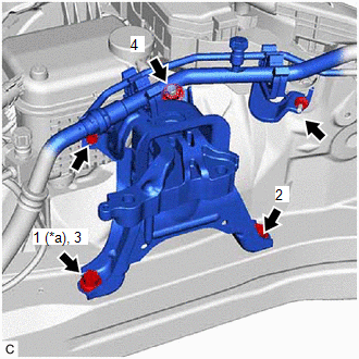
Image 178
*a
Temporarily Tighten
b. Install the 2 bolts and nut in the order shown in the illustration.
Torque: 72 N*m (734 kgf*cm, 53 ft.*lbf)
c. Connect the air conditioner tube and accessory assembly to the engine mounting insulator sub-assembly RH with the bolt and nut.
Torque: 9.8 N*m (100 kgf*cm, 87 in.*lbf)
d. Install the No. 2 earth wire to the engine mounting insulator sub-assembly RH and vehicle with the 2 bolts.
Torque: 10.5 N*m (107 kgf*cm, 8 ft.*lbf)
23. INSTALL ENGINE MOUNTING INSULATOR LH
HINT:
Perform this procedure only when replacement of the engine mounting insulator LH is necessary.
a. Temporarily install the engine mounting insulator LH to the vehicle.
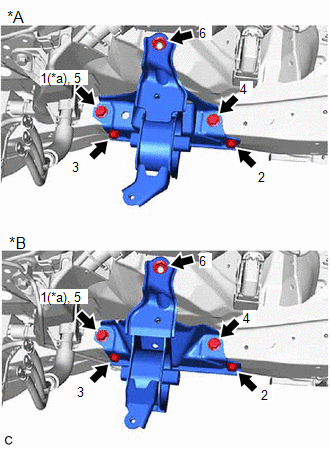
Image 179
*A
for CVT
*B
for Manual Transaxle
*a
Temporarily Tighten
b. Install the 4 bolts and nut in the order shown in the illustration.
Torque: 42 N*m (428 kgf*cm, 31 ft.*lbf)
24. REMOVE ENGINE HANGERS
See step 62
25. INSTALL WIRE HARNESS CLAMP BRACKET
a. Install the wire harness clamp bracket with the bolt.
Torque: 39 N*m (398 kgf*cm, 29 ft.*lbf)
b. Connect the air fuel ratio sensor connector.
c. Engage the 4 clamps.
26. INSTALL ENGINE ASSEMBLY WITH TRANSAXLE
a. Using height adjustment attachments and plate lift attachments to keep the engine assembly with transaxle and front suspension crossmember sub-assembly
engine lifter underneath the engine assembly with transaxle and front suspension crossmember sub-assembly.
NOTE:
Using height adjustment attachments and plate lift attachments, keep the engine assembly with transaxle horizo
Do not perform any procedures while the engine assembly is suspended because doing so may cause the engin
to drop, resulting in injury. However, the engine assembly needs to be suspended when it is installed to or remo
engine stand.
To prevent the oil pan sub-assembly from deforming, do not place any attachments under the oil pan sub-assem
engine assembly with transaxle.
b. Operate the engine lifter and install the engine assembly with transaxle to the vehicle.
WARNING:
Do not raise the engine assembly with transaxle more than necessary. If the engine is raised excessively, the vehicle
lifted up.
Bolt
Torque: 72 N*m (734 kgf*cm, 53 ft.*lbf)
Nut
Torque: 41 N*m (418 kgf*cm, 30 ft.*lbf)
27. INSTALL REAR SIDE RAIL REINFORCEMENT SUB-ASSEMBLY LH
Refer to PROCEDURE - Step 18
28. INSTALL REAR SIDE RAIL REINFORCEMENT SUB-ASSEMBLY RH
HINT:
Use the same procedure as for the LH side.
29. INSTALL DRIVE PLATE AND TORQUE CONVERTER ASSEMBLY SETTING BOLT (for CVT)
Refer to PROCEDURE - Step 15
30. INSTALL FLYWHEEL HOUSING UNDER COVER
a. Install the flywheel housing under cover to the stiffening crankcase assembly.
31. CONNECT NO. 1 CLUTCH HOSE (for Manual Transaxle)
a. Connect the No. 1 clutch hose to the clutch flexible hose bracket with a new clip.
b. Using a 10 mm union nut wrench, connect the bleeder clutch release tube to the No. 1 clutch hose.
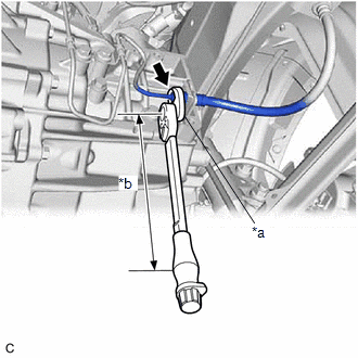
Image 180
*a
10 mm Union Nut Wrench
*b
Torque Wrench Fulcrum Length
Specified tightening torque
Torque: 15.2 N*m (155 kgf*cm, 11 ft.*lbf)
Refer to PROCEDURE - Step 17
35. CONNECT NO. 2 STEERING INTERMEDIATE SHAFT ASSEMBLY
Refer to PROCEDURE - Step 5 [01/2019 - 09/2019] , or refer to PROCEDURE - Step 5 [09/2019 - ]
36. INSTALL COLUMN HOLE COVER SILENCER SHEET
Refer to PROCEDURE - Step 6 [01/2019 - 09/2019] , or refer to PROCEDURE - Step 6 [09/2019 - ]
37. CONNECT SUCTION HOSE SUB-ASSEMBLY
Refer to PROCEDURE - Step 4
38. CONNECT DISCHARGE HOSE SUB-ASSEMBLY
Refer to PROCEDURE - Step 3
39. CONNECT FUEL TUBE SUB-ASSEMBLY
a. Connect the fuel tube sub-assembly to the fuel pipe.
Refer to PRECAUTION [03/2019 - ]
b. Engage the claw and install the No. 1 fuel pipe clamp.
40. CONNECT INLET HEATER WATER HOSE
a. Connect the inlet heater water hose to the No. 1 water by-pass pipe and slide the clip to secure it.
41. CONNECT OUTLET HEATER WATER HOSE
a. Connect the outlet heater water hose to the No. 3 water by-pass hose and slide the clip to secure it.
b. Engage the clamp.
42. CONNECT CHECK VALVE TO CONNECTOR TUBE HOSE
for TMC Made:
Refer to PROCEDURE - Step 2
for TMMMS Made:
Refer to PROCEDURE - Step 2
43. CONNECT FUEL VAPOR FEED HOSE
a. Connect the fuel vapor feed hose to the purge valve (purge VSV) and slide the clip to secure it.
44. CONNECT FLOOR SHIFT TRANSMISSION CONTROL SELECT CABLE (for CVT)
Refer to PROCEDURE - Step 2
45. CONNECT TRANSMISSION CONTROL CABLE ASSEMBLY (for Manual Transaxle)
a. Install the transmission control cable assembly to the control cable bracket assembly with 2 new clips (B).
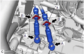
Image 181
b. Engage the clamp to connect the engine wire to the battery clamp sub-assembly.
49. CONNECT WIRE HARNESS
a. Connect the engine wire to the positive (+) battery terminal with the 3 nuts.
Torque: 7.6 N*m (77 kgf*cm, 67 in.*lbf)
b. Connect the engine wire to the battery clamp sub-assembly with the bolt and nut.
Torque: 7.0 N*m (71 kgf*cm, 62 in.*lbf)
c. Connect the engine wire to the vehicle with the 2 bolts.
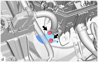
Image 182
Torque: 10 N*m (102 kgf*cm, 7 ft.*lbf)
50. INSTALL ECM
Refer to INSTALLATION [01/2019 - ]
51. INSTALL BATTERY
Refer to INSTALLATION [01/2019 - ]
52. BLEED CLUTCH LINE (for Manual Transaxle)
Refer to PROCEDURE - Step 4
53. ADD ENGINE OIL
Refer to PROCEDURE - Step 5
54. ADD ENGINE COOLANT
Refer to PROCEDURE - Step 2
55. ADD MANUAL TRANSAXLE OIL (for Manual Transaxle)
Refer to PROCEDURE - Step 4
56. ADD CONTINUOUSLY VARIABLE TRANSAXLE FLUID (for CVT)
Refer to ADJUSTMENT [01/2019 - ]
57. CHARGE AIR CONDITIONING SYSTEM WITH REFRIGERANT
for HFO-1234yf(R1234yf):
Refer to PROCEDURE - Step 2 [01/2019 - 06/2020] , or refer to PROCEDURE - Step 2 [06/2020 - ]
for HFC-134a(R134a):
61. INSPECT SHIFT LEVER POSITION (for CVT)
Refer to PROCEDURE - Step 2
62. ADJUST SHIFT LEVER POSITION (for CVT)
Refer to PROCEDURE - Step 3
63. INSPECT FOR ENGINE OIL LEAK
Refer to PROCEDURE - Step 4
64. INSPECT FOR COOLANT LEAK
Refer to PROCEDURE - Step 1
| 65. | INSPECT FOR CONTINUOUSLY VARIABLE TRANSAXLE FLUID LEAK (for CVT) |
|---|---|
| 66. | INSPECT FOR MANUAL TRANSAXLE OIL LEAK (for Manual Transaxle) |
| 67. | INSPECT FOR REFRIGERANT LEAK |
for HFO-1234yf(R1234yf):
Refer to PROCEDURE - Step 5 [01/2019 - 06/2020] , or refer to PROCEDURE - Step 5 [06/2020 - ]
for HFC-134a(R134a):
Refer to PROCEDURE - Step 4
68. INSPECT FOR FUEL LEAK
Refer to PROCEDURE - Step 1
69. INSPECT FOR EXHAUST GAS LEAK
Refer to PROCEDURE - Step 7
70. CHECK ENGINE OIL LEVEL
Refer to PROCEDURE - Step 3
71. INSPECT RADIATOR RESERVE TANK ENGINE COOLANT LEVEL
Refer to PROCEDURE - Step 2
72. INSTALL REAR ENGINE UNDER COVER LH
a. Type A:
1. Install the rear engine under cover LH to the vehicle with the 4 clips.
2. Install the screw.
b. Type B:
1. Install the rear engine under cover LH to the vehicle with the 5 clips.
2. Install the screw.
73. INSTALL REAR ENGINE UNDER COVER RH
a. Type A:
1. Install the rear engine under cover RH to the vehicle with the 4 clips.
2. Install the screw.
b. Type B:
1. Install the rear engine under cover RH to the vehicle with the 5 clips.
2. Install the screw.
74. INSTALL NO. 1 ENGINE UNDER COVER ASSEMBLY
a. Install the No. 1 engine under cover assembly to the vehicle with the 10 clips.
b. Install the 4 bolts.
Torque: 7.5 N*m (76 kgf*cm, 66 in.*lbf)
75. INSTALL FRONT WHEELS
Refer to INSTALLATION [03/2019 - ]
81. INSPECT CO/HC
See step 11
82. CHECK SPEED SENSOR SIGNAL
Refer to TEST MODE PROCEDURE [06/2018 - ]
ENGINE UNIT
PRECAUTION [01/2019 - ]
PRECAUTION [01/2019 - ]
HINT:
Any digits beyond the 0.01 mm (1/1000 in.) place for standard, minimum and maximum values should be used as a reference only.
When both standard and maximum or minimum values are listed for an inspection, use the standard value as a reference only and base any judgments on the maxi
minimum values.
COMPONENTS [01/2019 - 03/2019]
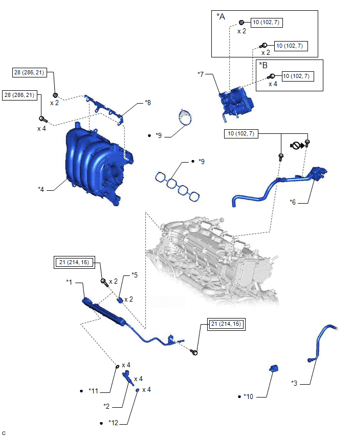
Image 183
Fig. 36: Engine Unit Replacement Components With Torque Specifications (1 Of 9) [01/2019 - 03/2019]
Courtesy of В© TOYOTA, LICENSE AGREEMENT TMS1002
*A
w/ Stud Bolt
*B
w/o S
Bolt
*11
O-RING
*12
INJEC
VIBR
INSU

Image 184
Tightening torque for
"Major areas involving
basic vehicle performance
such as
moving/turning/stopping":
N*m (kgf*cm, ft.*lbf)

Image 185
N*m
(kgf*c
ft.*lbf
Speci
torque
•
Non-reusable part

Image 186
Do no
lubric
the th
parts
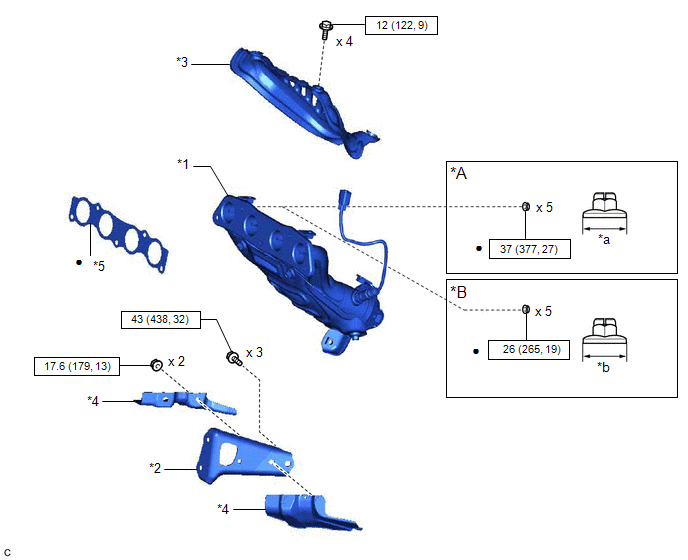
Image 187
Fig. 37: Engine Unit Replacement Components With Torque Specifications (2 Of 9) [01/2019 - 03/2019]
Courtesy of В© TOYOTA, LICENSE AGREEMENT TMS1002
*A
Type A
*B
Type B
*1
EXHAUST MANIFOLD
*2
MANIFOLD STAY
*3
NO. 1 EXHAUST MANIFOLD HEAT
INSULATOR
*4
DRIVE SHAFT HEAT INSULATOR
ASSEMBLY
*5
EXHAUST MANIFOLD TO HEAD
GASKET
-
-
*a
18 mm (0.709 in.)
*b
17 mm (0.669 in.)

Image 188
N*m (kgf*cm, ft.*lbf): Specified torque
•
Non-reusable part
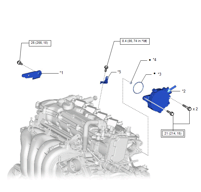
Image 189
Fig. 38: Engine Unit Replacement Components With Torque Specifications (3 Of 9) [01/2019 - 03/2019]
Courtesy of В© TOYOTA, LICENSE AGREEMENT TMS1002
*1
NO. 2 GENERATOR
BRACKET
*2
VACU
PUMP
ASSE
*3
NO. 2 O-RING
*4
NO. 3
RING
*5
WIRE HARNESS
CLAMP BRACKET
-

Image 190
Tightening torque for
"Major areas involving
basic vehicle performance
such as
moving/turning/stopping":
N*m (kgf*cm, ft.*lbf)

Image 191
N*m
(kgf*c
ft.*lbf
Speci
torque
•
Non-reusable part
-
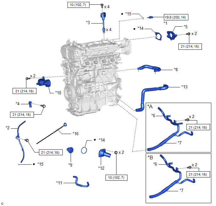
Image 192
Fig. 39: Engine Unit Replacement Components With Torque Specifications (4 Of 9) [01/2019 - 03/2019]
Courtesy of В© TOYOTA, LICENSE AGREEMENT TMS1002
*A
for CVT
*B
for Manual Transaxle
*1
ENGINE COOLANT TEMPERATURE
SENSOR
*2
ENGINE OIL LEVEL DIPSTICK GU
*3
IGNITION COIL ASSEMBLY
*4
KNOCK CONTROL SENSOR
*5
NO. 1 VACUUM PUMP BRACKET
*6
NO. 1 WATER BY-PASS PIPE
*7
NO. 3 WATER BY-PASS HOSE
*8
VENTILATION HOSE
*9
THERMOSTAT
*10
V-RIBBED BELT TENSIONER
ASSEMBLY
*11
WATER BY-PASS HOSE
*12
WATER INLET
*13
WATER INLET HOSE
*14
GASKET
*15
O-RING
*16
ENGINE OIL LEVEL DIPSTICK

Image 193
N*m (kgf*cm, ft.*lbf): Specified torque
•
Non-reusable part
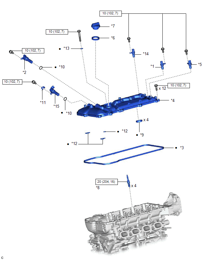
Image 194
Fig. 40: Engine Unit Replacement Components With Torque Specifications (5 Of 9) [01/2019 - 03/2019]
Courtesy of В© TOYOTA, LICENSE AGREEMENT TMS1002
*1
CAMSHAFT POSITION SENSOR (for
Intake Side)
*2
CAMSHAFT TIMING OIL CONTRO
VALVE ASSEMBLY (for Intake Side
*3
CYLINDER HEAD COVER GASKET
*4
CYLINDER HEAD COVER SUB-
ASSEMBLY
*5
VALVEMATIC SHAFT SENSOR (CAM
POSITION SENSOR)
*6
OIL FILLER CAP GASKET
*7
OIL FILLER CAP SUB-ASSEMBLY
*8
SPARK PLUG
*9
SPARK PLUG TUBE GASKET
*10
O-RING
*11
BRACKET
*12
GASKET
*13
SEAL WASHER
*14
CAMSHAFT POSITION SENSOR (
Exhaust Side)
*15
CAMSHAFT TIMING OIL CONTROL
VALVE ASSEMBLY (for Exhaust Side)
-
-

Image 195
N*m (kgf*cm, ft.*lbf): Specified torque
•
Non-reusable part
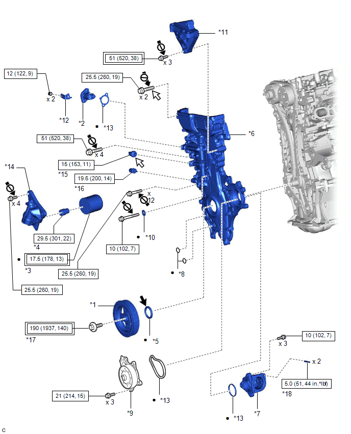
Image 196
Fig. 41: Engine Unit Replacement Components With Torque Specifications (6 Of 9) [01/2019 - 03/2019]
Courtesy of В© TOYOTA, LICENSE AGREEMENT TMS1002
*1
CRANKSHAFT
PULLEY
*2
NO. 1
TENS
ASSE
*3
OIL FILTER SUB-
ASSEMBLY
*4
OIL F
UNIO
*5
TIMING CHAIN
COVER OIL SEAL
*6
TIMIN
COVE
ASSE
*7
WATER INLET
HOUSING
*8
O-RIN
*9
ENGINE WATER PUMP
ASSEMBLY
*10
SEAL
*11
ENGINE MOUNTING
BRACKET RH
*12
BRAC
*13
GASKET
*14
OIL F
BRAC
*15
ENGINE OIL
PRESSURE SWITCH
ASSEMBLY
*16
ENGI
TEMP
SENS
*17
CRANKSHAFT
PULLEY SET BOLT
*18
WATE
HOUS
STUD

Image 197
Tightening torque for
"Major areas involving
basic vehicle performance
such as
moving/turning/stopping":
N*m (kgf*cm, ft.*lbf)

Image 198
N*m
ft.*lbf
torque
•
Non-reusable part

Image 199
MP gr

Image 200
Adhesive 1324
*
Preco

Image 201
Do not apply lubricants to
the threaded parts
-
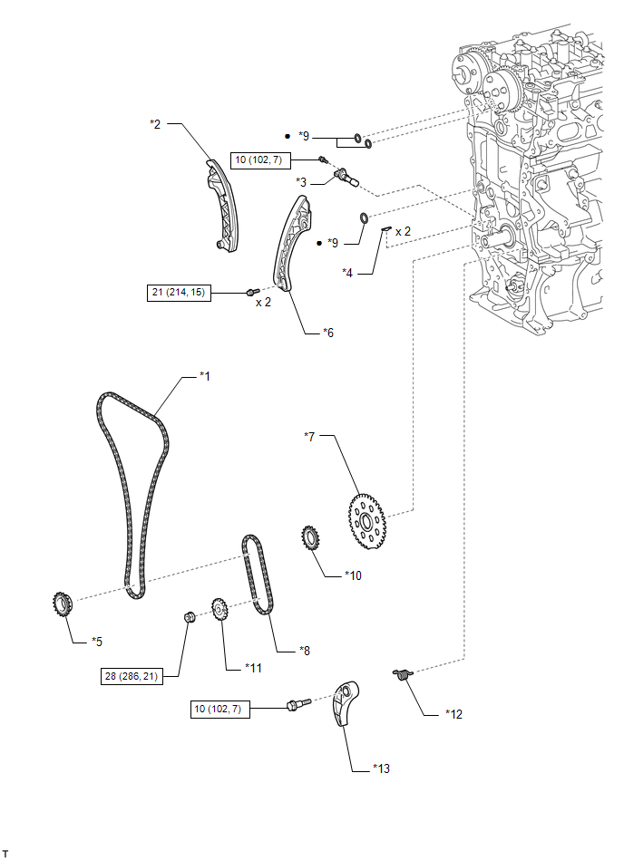
Image 202
Fig. 42: Engine Unit Replacement Components With Torque Specifications (7 Of 9) [01/2019 - 03/2019]
Courtesy of В© TOYOTA, LICENSE AGREEMENT TMS1002
*1
CHAIN SUB-ASSEMBLY
*2
CHAIN TENSIONER SLIPPER
*3
CRANKSHAFT POSITION SENSOR
*4
CRANKSHAFT TIMING GEAR KEY
*5
CRANKSHAFT TIMING SPROCKET
*6
NO. 1 CHAIN VIBRATION DAMPER
*7
NO. 1 CRANKSHAFT POSITION
SENSOR PLATE
*8
NO. 2 CHAIN SUB-ASSEMBLY
*9
O-RING
*10
OIL PUMP DRIVE GEAR
*11
OIL PUMP DRIVE SHAFT GEAR
*12
CHAIN DAMPER SPRING
*13
CHAIN TENSIONER PLATE
-
-

Image 203
N*m (kgf*cm, ft.*lbf): Specified torque
•
Non-reusable part
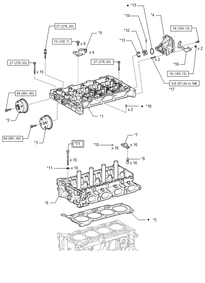
Image 204
Fig. 43: Engine Unit Replacement Components With Torque Specifications (8 Of 9) [01/2019 - 03/2019]
Courtesy of В© TOYOTA, LICENSE AGREEMENT TMS1002
*1
CAMSHAFT HOUSING
SUB-ASSEMBLY
*2
CAM
TIMIN
EXHA
ASSE
*3
CAMSHAFT TIMING
GEAR ASSEMBLY
*4
CONT
VARI
VALV
CONT
ASSE
*13
VALVE LIFT CONTROL
ACTUATOR CLIP
*14
STRA
*15
O-RING
*16
WIRE
CLAM
BRAC
*17
STUD BOLT
*18
CAM
HOUS
STRA

Image 205
Tightening torque for
"Major areas involving
basic vehicle performance
such as
moving/turning/stopping":
N*m (kgf*cm, ft.*lbf)

Image 206
N*m
ft.*lbf
torque
•
Non-reusable part
-
*T1
1st: 49 (500, 36)
2nd: Turn 90В°
3rd: Turn 45В°
-
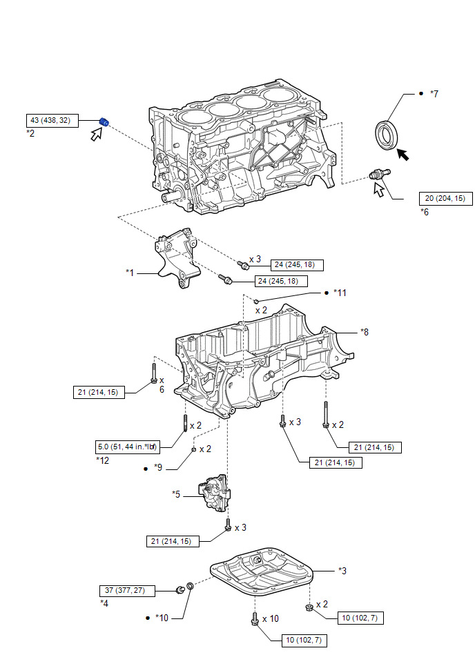
Image 207
Fig. 44: Engine Unit Replacement Components With Torque Specifications (9 Of 9) [01/2019 - 03/2019]
Courtesy of В© TOYOTA, LICENSE AGREEMENT TMS1002
*1
NO. 1
GENERATOR
BRACKET
*2
NO. 1 TAPER
SCREW PLUG
*3
NO. 2 OIL PAN
SUB-
ASSEMBLY
*4
OIL PAN DRA
PLUG
*5
OIL PUMP
ASSEMBLY
*6
PCV VALVE
(VENTILATIO
VALVE SUB-
ASSEMBLY)
*7
REAR ENGINE
OIL SEAL
*8
STIFFENING
CRANKCASE
ASSEMBLY
*9
STIFFENING
CRANKCASE
RING PIN
*10
GASKET
*11
RING PIN
*12
STUD BOLT

Image 208
N*m (kgf*cm,
ft.*lbf): Specified
torque
•
Non-reusable p

Image 209
MP grease

Image 210
Adhesive 1324
*
Precoated part
-
-
COMPONENTS [03/2019 - ]
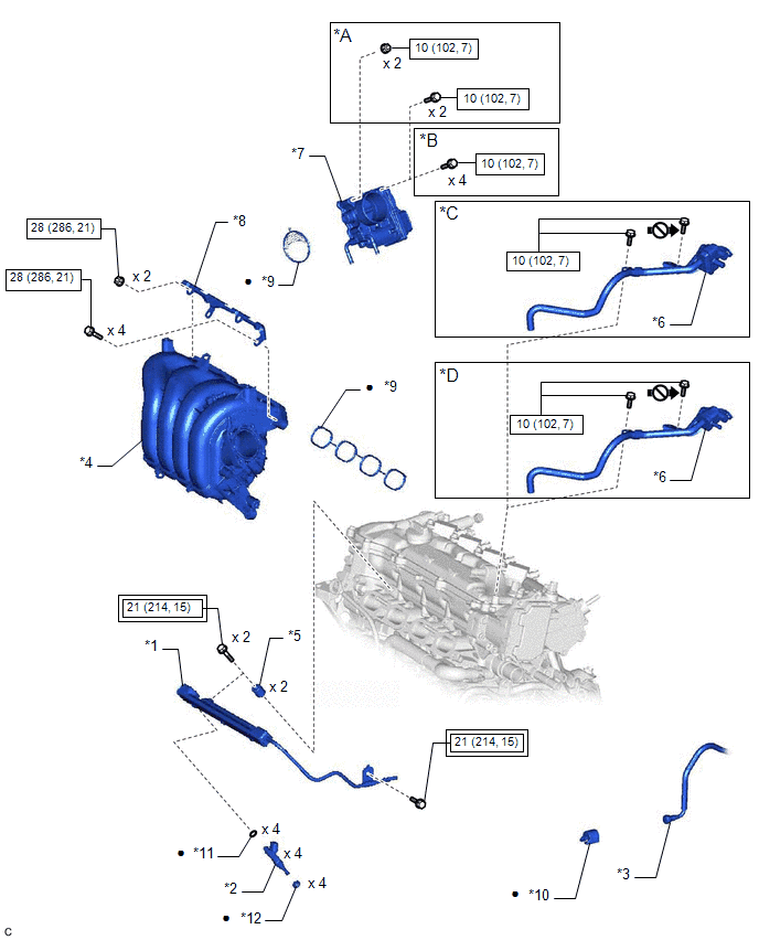
Image 211
Fig. 45: Engine Unit Replacement Components With Torque Specifications (1 Of 11) [03/2019 - ]
Courtesy of В© TOYOTA, LICENSE AGREEMENT TMS1002
*A
w/ Stud Bolt
*B
w/o S
Bolt
*C
w/ Canister Pump Module
*D
w/o C
Pump
Modu
*1
FUEL DELIVERY PIPE
SUB-ASSEMBLY
*2
FUEL
INJEC
ASSE
*3
FUEL TUBE SUB-
ASSEMBLY
*4
INTA
MAN
*5
NO. 1 DELIVERY PIPE
SPACER
*6
PURG
VALV
(PUR
VSV)
*7
THROTTLE BODY
ASSEMBLY
*8
INTA
MAN
STAY
*9
GASKET
*10
NO. 2
PIPE
CLAM
*11
O-RING
*12
INJEC
VIBR
INSU

Image 212
Tightening torque for
"Major areas involving
basic vehicle performance
such as
moving/turning/stopping":
N*m (kgf*cm, ft.*lbf)

Image 213
N*m
(kgf*c
ft.*lbf
Speci
torque
•
Non-reusable part

Image 214
Do no
lubric
the th
parts
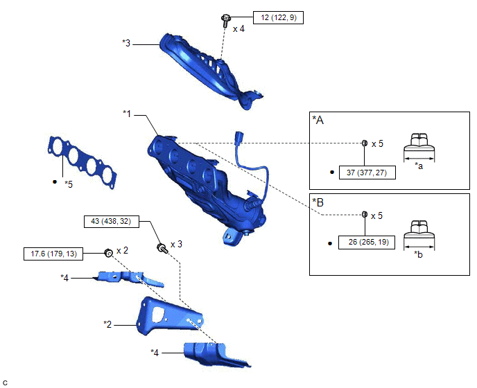
Image 215
Fig. 46: Engine Unit Replacement Components With Torque Specifications (2 Of 11) [03/2019 - ]
Courtesy of В© TOYOTA, LICENSE AGREEMENT TMS1002

Image 216
N*m (kgf*cm, ft.*lbf): Specified torque
•
Non-reusable part
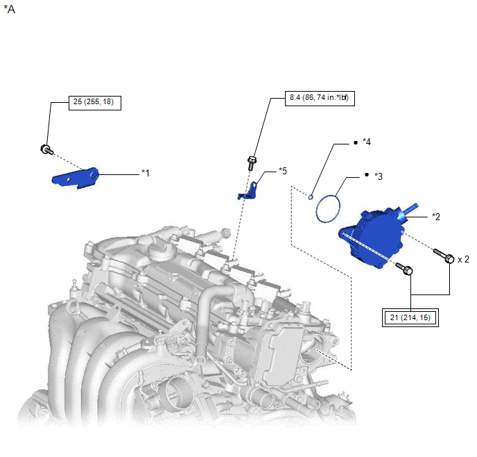
Image 217
Fig. 47: Engine Unit Replacement Components With Torque Specifications (3 Of 11) [03/2019 - ]
Courtesy of В© TOYOTA, LICENSE AGREEMENT TMS1002
*A
for TMC Made
-
*1
NO. 2 GENERATOR
BRACKET
*2
VACU
PUMP
ASSE
*3
NO. 2 O-RING
*4
NO. 3
RING
*5
WIRE HARNESS
CLAMP BRACKET
-

Image 218
Tightening torque for
"Major areas involving
basic vehicle performance
such as
moving/turning/stopping":
N*m (kgf*cm, ft.*lbf)

Image 219
N*m
(kgf*c
ft.*lbf
Speci
torque
•
Non-reusable part
-
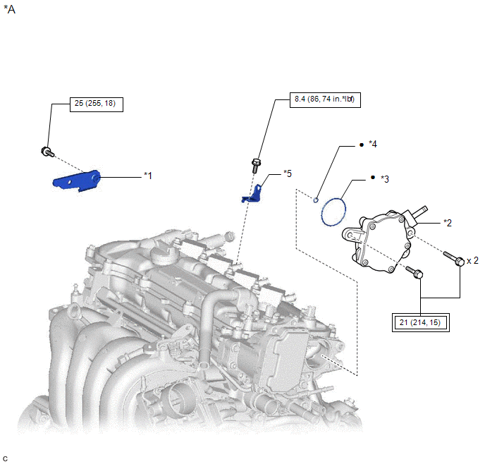
Image 220
Fig. 48: Engine Unit Replacement Components With Torque Specifications (4 Of 11) [03/2019 - ]
Courtesy of В© TOYOTA, LICENSE AGREEMENT TMS1002
*A
for TMMMS Made
-
*1
NO. 2 GENERATOR
BRACKET
*2
VACU
PUMP
ASSE
*3
NO. 2 O-RING
*4
NO. 1
RING
*5
WIRE HARNESS
CLAMP BRACKET
-

Image 221
Tightening torque for
"Major areas involving
basic vehicle performance
such as
moving/turning/stopping":
N*m (kgf*cm, ft.*lbf)

Image 222
N*m
(kgf*c
ft.*lbf
Speci
torque
•
Non-reusable part
-
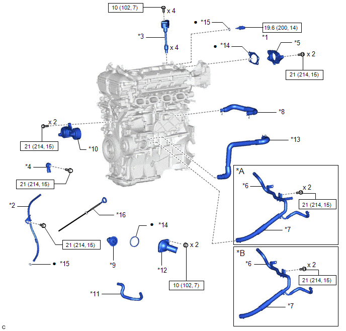
Image 223
Fig. 49: Engine Unit Replacement Components With Torque Specifications (5 Of 11) [03/2019 - ]
Courtesy of В© TOYOTA, LICENSE AGREEMENT TMS1002
*A
for CVT
*B
for Manual Transaxle
*1
ENGINE COOLANT TEMPERATURE
SENSOR
*2
ENGINE OIL LEVEL DIPSTICK GU
*3
IGNITION COIL ASSEMBLY
*4
KNOCK CONTROL SENSOR
*5
NO. 1 VACUUM PUMP BRACKET
*6
NO. 1 WATER BY-PASS PIPE
*7
NO. 3 WATER BY-PASS HOSE
*8
VENTILATION HOSE
*9
THERMOSTAT
*10
V-RIBBED BELT TENSIONER
ASSEMBLY
*11
WATER BY-PASS HOSE
*12
WATER INLET
*13
WATER INLET HOSE
*14
GASKET
*15
O-RING
*16
ENGINE OIL LEVEL DIPSTICK

Image 224
N*m (kgf*cm, ft.*lbf): Specified torque
•
Non-reusable part
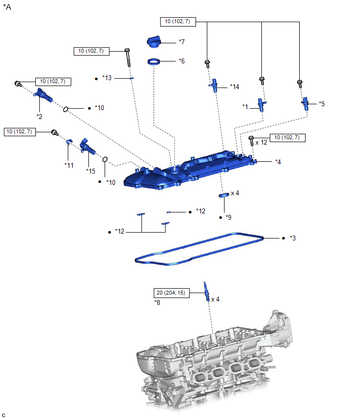
Image 225
Fig. 50: Engine Unit Replacement Components With Torque Specifications (6 Of 11) [03/2019 - ]
Courtesy of В© TOYOTA, LICENSE AGREEMENT TMS1002
*A
w/ Canister Pump Module
-
-
*1
CAMSHAFT POSITION SENSOR (for
Intake Side)
*2
CAMSHAFT TIMING OIL CONTRO
VALVE ASSEMBLY (for Intake Side
*3
CYLINDER HEAD COVER GASKET
*4
CYLINDER HEAD COVER SUB-
ASSEMBLY
*5
VALVEMATIC SHAFT SENSOR (CAM
POSITION SENSOR)
*6
OIL FILLER CAP GASKET
*7
OIL FILLER CAP SUB-ASSEMBLY
*8
SPARK PLUG
*9
SPARK PLUG TUBE GASKET
*10
O-RING
*11
BRACKET
*12
GASKET

Image 226
N*m (kgf*cm, ft.*lbf): Specified torque
•
Non-reusable part
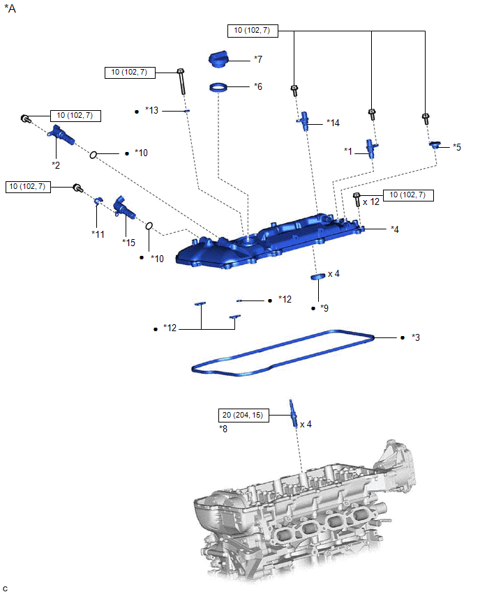
Image 227
Fig. 51: Engine Unit Replacement Components With Torque Specifications (7 Of 11) [03/2019 - ]
Courtesy of В© TOYOTA, LICENSE AGREEMENT TMS1002
*A
w/o Canister Pump Module
-
-
*1
CAMSHAFT POSITION SENSOR (for
Intake Side)
*2
CAMSHAFT TIMING OIL CONTRO
VALVE ASSEMBLY (for Intake Side)
*3
CYLINDER HEAD COVER GASKET
*4
CYLINDER HEAD COVER SUB-
ASSEMBLY
*5
CYLINDER HEAD COVER SCREEN
*6
OIL FILLER CAP GASKET
*7
OIL FILLER CAP SUB-ASSEMBLY
*8
SPARK PLUG
*9
SPARK PLUG TUBE GASKET
*10
O-RING
*11
BRACKET
*12
GASKET

Image 228
N*m (kgf*cm, ft.*lbf): Specified torque
•
Non-reusable part
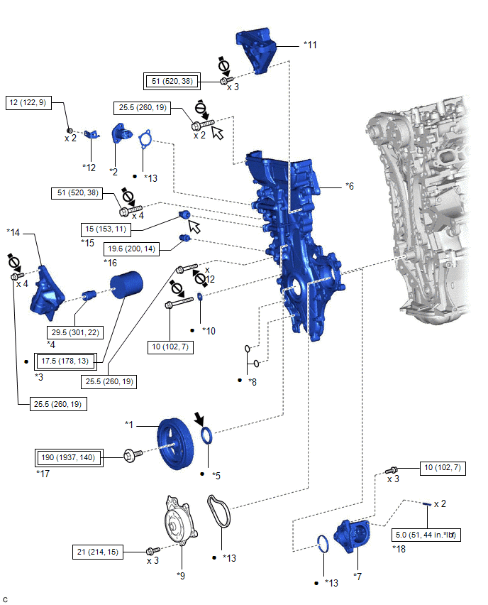
Image 229
Fig. 52: Engine Unit Replacement Components With Torque Specifications (8 Of 11) [03/2019 - ]
Courtesy of В© TOYOTA, LICENSE AGREEMENT TMS1002
*1
CRANKSHAFT
PULLEY
*2
NO. 1
TENS
ASSE
*3
OIL FILTER SUB-
ASSEMBLY
*4
OIL F
UNIO
*5
TIMING CHAIN
COVER OIL SEAL
*6
TIMIN
COVE
ASSE
*7
WATER INLET
HOUSING
*8
O-RIN

Image 230
Tightening torque for
"Major areas involving
basic vehicle performance
such as
moving/turning/stopping":
N*m (kgf*cm, ft.*lbf)

Image 231
N*m
ft.*lbf
torque
•
Non-reusable part

Image 232
MP gr

Image 233
Adhesive 1324
*
Preco

Image 234
Do not apply lubricants to
the threaded parts
-
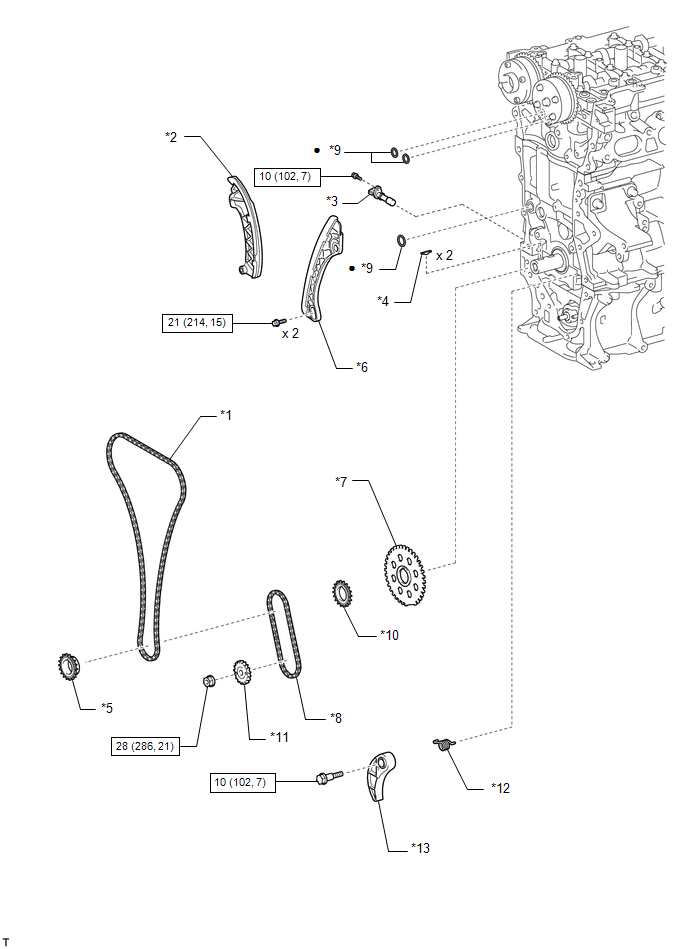
Image 235
Fig. 53: Engine Unit Replacement Components With Torque Specifications (9 Of 11) [03/2019 - ]
Courtesy of В© TOYOTA, LICENSE AGREEMENT TMS1002
*1
CHAIN SUB-ASSEMBLY
*2
CHAIN TENSIONER SLIPPER
*3
CRANKSHAFT POSITION SENSOR
*4
CRANKSHAFT TIMING GEAR KEY
*5
CRANKSHAFT TIMING SPROCKET
*6
NO. 1 CHAIN VIBRATION DAMPER
*7
NO. 1 CRANKSHAFT POSITION
SENSOR PLATE
*8
NO. 2 CHAIN SUB-ASSEMBLY
*9
O-RING
*10
OIL PUMP DRIVE GEAR
*11
OIL PUMP DRIVE SHAFT GEAR
*12
CHAIN DAMPER SPRING
*13
CHAIN TENSIONER PLATE
-
-

Image 236
N*m (kgf*cm, ft.*lbf): Specified torque
•
Non-reusable part
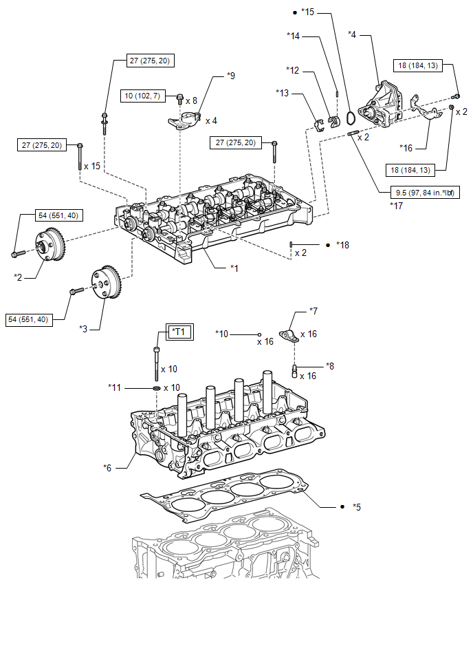
Image 237
Fig. 54: Engine Unit Replacement Components With Torque Specifications (10 Of 11) [03/2019 - ]
Courtesy of В© TOYOTA, LICENSE AGREEMENT TMS1002
*1
CAMSHAFT HOUSING
SUB-ASSEMBLY
*2
CAM
TIMIN
EXHA
ASSE
*3
CAMSHAFT TIMING
GEAR ASSEMBLY
*4
CONT
VARI
VALV
CONT
ASSE
*13
VALVE LIFT CONTROL
ACTUATOR CLIP
*14
STRA
*15
O-RING
*16
WIRE
CLAM
BRAC
*17
STUD BOLT
*18
CAM
HOUS
STRA

Image 238
Tightening torque for
"Major areas involving
basic vehicle performance
such as
moving/turning/stopping":
N*m (kgf*cm, ft.*lbf)

Image 239
N*m
ft.*lbf
torque
•
Non-reusable part
-
*T1
1st: 49 (500, 36)
2nd: Turn 90В°
3rd: Turn 45В°
-
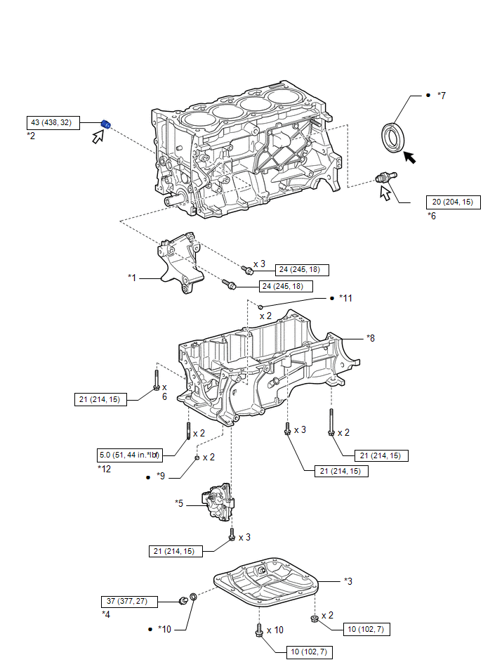
Image 240
Fig. 55: Engine Unit Replacement Components With Torque Specifications (11 Of 11) [03/2019 - ]
Courtesy of В© TOYOTA, LICENSE AGREEMENT TMS1002
*1
NO. 1
GENERATOR
BRACKET
*2
NO. 1 TAPER
SCREW PLUG
*3
NO. 2 OIL PAN
SUB-
ASSEMBLY
*4
OIL PAN DRA
PLUG
*5
OIL PUMP
ASSEMBLY
*6
PCV VALVE
(VENTILATIO
VALVE SUB-
ASSEMBLY)
*7
REAR ENGINE
OIL SEAL
*8
STIFFENING
CRANKCASE
ASSEMBLY
*9
STIFFENING
CRANKCASE
RING PIN
*10
GASKET
*11
RING PIN
*12
STUD BOLT

Image 241
N*m (kgf*cm,
ft.*lbf): Specified
torque
•
Non-reusable p

Image 242
MP grease

Image 243
Adhesive 1324
*
Precoated part
-
-
REMOVAL [01/2019 - 03/2019]
CAUTION / NOTICE / HINT
The necessary procedures (adjustment, calibration, initialization, or registration) that must be performed after parts are removed and installed, or replaced during engine
removal/installation are shown below.
NECESSARY PROCEDURES AFTER PARTS REMOVED/INSTALLED/REPLACED
Replaced Part or Performed Procedure
Necessary Procedure
Effect/Inoperative Function when
Necessary Procedure not Performed
Link
Battery terminal is disconnected/reconnected
Perform steering sensor zero point calibration
Lane Control System
Refer to INITIALIZAT
[06/2018 - ]
Pre-collision System
Lighting System (w/ AFS) (EXT)
Replacement of ECM
Vehicle Identification Number (VIN)
registration
MIL comes on
Refer to REGISTRATI
[01/2019 - ]
ECU communication ID registration
(Immobiliser system)
Engine start function
Refer to REGISTRATI
[01/2019 - 09/2019]
1. Reset memory
2. Deceleration sensor zero point
calibration
3. CVT oil pressure calibration
Large shift shock
Deterioration of fuel efficiency
Refer to INITIALIZAT
[01/2019 - ]
Replacement of ECM*1
Code registration (Smart Key System (for
Gasoline Model, Start Function))
Wireless Door Lock Control System
(for Gasoline Model with Smart Key
System)
Smart Key System (for Gasoline
Model, Entry Function)
Smart Key System (for Gasoline
Model, Start Function)
Steering lock function
Refer to REGISTRATI
[01/2019 - 09/2019]
Replacement of throttle body assembly
Replacement of engine assembly
Replacement of cylinder head sub-
assembly
Replacement of camshaft timing gear
assembly
Replacement of camshaft timing exhaust
gear assembly
Replacement of fuel injector assembly
Replacement of spark plug
Replacement of ignition coil assembly
Gas leak from exhaust system is repaired
Replacement of knock control sensor
Replacement of engine coolant
temperature sensor
Replacement of continuously variable
valve lift controller assembly
Inspection After Repair
Poor idle, etc.
Engine start function, etc.
Refer to INITIALIZAT
[01/2019 - ]
Suspension, tires, etc.
(The vehicle height changes because of
suspension or tire replacement)
Perform headlight ECU sub-assembly LH
initialization
Lighting system (w/ AFS) (EXT)
Refer to INITIALIZAT
[06/2018 - ]
Front wheel alignment adjustment
1. Perform "Reset Memory".
2. Perform acceleration sensor zero point
calibration and store system
information memorization.
VSC is disabled or malfunctions
DTCs are output
Slip indicator light illuminates
ABS warning light illuminates
w/ Electric Parking Bra
System: Refer to UTILI
[06/2018 - ]
w/o Electric Parking Br
System: Refer to UTILI
[01/2019 - 03/2019]
CVT fluid
ATF thermal degradation estimate reset
The value of the Data List item "ATF
Thermal Degradation Estimate" is not
estimated correctly
Refer to INITIALIZAT
[01/2019 - ] for K313
*1: w/ Smart Key System
*2: w/o Smart Key System
NOTE:
After the ignition switch is turned off, the radio and display receiver assembly records various types of memory and settin
result, after turning the ignition switch off, make sure to wait at least 85 seconds before disconnecting the cable from the n
battery terminal. (for Audio and Visual System (for Gasoline Model))
After the engine switch is turned off, the radio and display receiver assembly records various types of memory and setting
result, after turning the engine switch off, make sure to wait at least 85 seconds before disconnecting the cable from the ne
battery terminal. (for Navigation System)
PROCEDURE
1. REMOVE THROTTLE BODY ASSEMBLY
Refer to PROCEDURE - Step 3
2. REMOVE INTAKE MANIFOLD
Refer to PROCEDURE - Step 3
3. REMOVE PURGE VALVE (PURGE VSV)
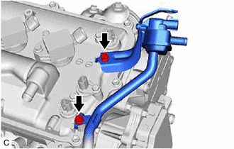
Image 244
Refer to PROCEDURE - Step 9
8. REMOVE ENGINE OIL LEVEL DIPSTICK GUIDE
a. Remove the engine oil level dipstick.
b. Remove the bolt and engine oil level dipstick guide.
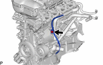
Image 245
c. Remove the O-ring from the engine oil level dipstick guide.
9. REMOVE NO. 1 EXHAUST MANIFOLD HEAT INSULATOR
Refer to PROCEDURE - Step 2
10. REMOVE DRIVE SHAFT HEAT INSULATOR SUB-ASSEMBLY
Refer to PROCEDURE - Step 3
11. REMOVE MANIFOLD STAY
Refer to PROCEDURE - Step 4
12. REMOVE EXHAUST MANIFOLD
Refer to PROCEDURE - Step 5
13. REMOVE VENTILATION HOSE
Refer to PROCEDURE - Step 2
14. DISCONNECT NO. 3 WATER BY-PASS HOSE
a. Slide the clip and disconnect the No. 3 water by-pass hose from the water inlet housing
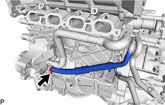
Image 246
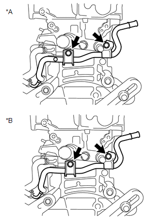
Image 247
*A
for CVT
*B
for Manual Transaxle
16. REMOVE WATER BY-PASS HOSE
a. Slide the clip and remove the water by-pass hose from the cylinder head sub-assembly.
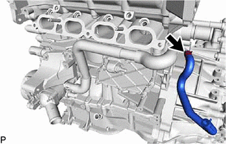
Image 248
17. REMOVE WATER INLET HOSE
a. Slide the 2 clips and remove the water inlet hose.
18. SEPARATE WATER INLET
Refer to PROCEDURE - Step 3
19. REMOVE THERMOSTAT
Refer to PROCEDURE - Step 4
20. REMOVE VACUUM PUMP ASSEMBLY
Refer to PROCEDURE - Step 3
21. REMOVE NO. 1 VACUUM PUMP BRACKET
a. Remove the 2 bolts, No. 1 vacuum pump bracket and gasket.
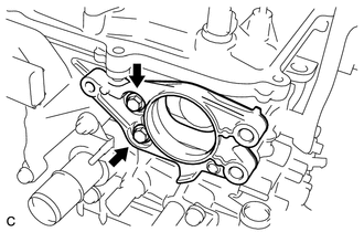
Image 249
22. REMOVE NO. 2 GENERATOR BRACKET
a. Remove the bolt and No. 2 generator bracket from the cylinder head sub-assembly.
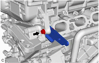
Image 250
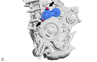
Image 251
24. REMOVE WIRE HARNESS CLAMP BRACKET
a. Remove the bolt and wire harness clamp bracket from the cylinder head cover sub-assembly.
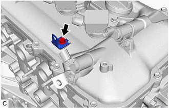
Image 252
25. REMOVE IGNITION COIL ASSEMBLY
Refer to PROCEDURE - Step 1
26. REMOVE ENGINE OIL TEMPERATURE SENSOR
Refer to PROCEDURE - Step 2
REMOVAL [03/2019 - ]
CAUTION / NOTICE / HINT
The necessary procedures (adjustment, calibration, initialization, or registration) that must be performed after parts are removed and installed, or replaced during engine
removal/installation are shown below.
NECESSARY PROCEDURES AFTER PARTS REMOVED/INSTALLED/REPLACED
Replaced Part or Performed Procedure
Necessary Procedure
Effect/Inoperative Function when
Necessary Procedure not Performed
Link
Battery terminal is disconnected/reconnected
Perform steering sensor zero point calibration
Lane Control System
Refer to INITIALIZAT
[06/2018 - ]
Pre-collision System
Lighting System (w/ AFS) (EXT)
Replacement of ECM
Vehicle Identification Number (VIN)
registration
MIL comes on
Refer to REGISTRATI
[01/2019 - ]
ECU communication ID registration
(Immobiliser system)
Engine start function
| Refer to | REGISTRATI |
|---|---|
| [01/2019 - 09/2019] | , or |
| to | REGISTRATION [09 |
- 04/2020] , or refer t
REGISTRATION [04/20
Replacement of ECM*2
Code registration (Immobiliser system)
Engine start
| Refer to | REGISTRATI |
|---|---|
| [01/2019 - 09/2019] | , or |
| to | REGISTRATION [09 |
- 04/2020] , or refer t
REGISTRATION [04/20
Replacement of throttle body assembly
Replacement of engine assembly
Replacement of cylinder head sub-
assembly
Replacement of camshaft timing gear
assembly
Replacement of camshaft timing exhaust
gear assembly
Replacement of fuel injector assembly
Replacement of spark plug
Replacement of ignition coil assembly
Gas leak from exhaust system is repaired
Replacement of knock control sensor
Replacement of engine coolant
temperature sensor
Replacement of continuously variable
valve lift controller assembly
Inspection After Repair
Poor idle, etc.
Engine start function, etc.
Refer to INITIALIZAT
[01/2019 - ]
Suspension, tires, etc.
(The vehicle height changes because of
suspension or tire replacement)
Perform headlight ECU sub-assembly LH
initialization
Lighting system (w/ AFS) (EXT)
Refer to INITIALIZAT
[06/2018 - ]
Front wheel alignment adjustment
1. Perform "Reset Memory".
2. Perform acceleration sensor zero point
calibration and store system
information memorization.
VSC is disabled or malfunctions
DTCs are output
Slip indicator light illuminates
ABS warning light illuminates
w/ Electric Parking Bra
System: Refer to UTILI
[06/2018 - ]
w/o Electric Parking Br
System: Refer to UTILI
[03/2019 - ]
CVT fluid
ATF thermal degradation estimate reset
The value of the Data List item "ATF
Thermal Degradation Estimate" is not
estimated correctly
Refer to INITIALIZAT
[01/2019 - ] for K313
*1: w/ Smart Key System
*2: w/o Smart Key System
NOTE:
After the ignition switch is turned off, the radio and display receiver assembly records various types of memory and settings. As
after turning the ignition switch off, make sure to wait at least 85 seconds before disconnecting the cable from the negative (-) b
terminal. (for Navigation System and Audio and Visual System (for Gasoline Model))
PROCEDURE
1. REMOVE THROTTLE BODY ASSEMBLY
Refer to PROCEDURE - Step 3
2. REMOVE INTAKE MANIFOLD
Refer to PROCEDURE - Step 3
3. REMOVE PURGE VALVE (PURGE VSV)
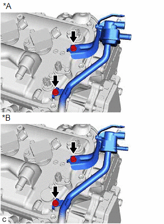
Image 253
*A
w/ Canister Pump Module
*B
w/o Canister Pump Module
a. Remove the 2 bolts and purge valve (purge VSV) from the cylinder head cover sub-assembly.
4. DISCONNECT FUEL TUBE SUB-ASSEMBLY
Refer to PROCEDURE - Step 5
5. REMOVE FUEL DELIVERY PIPE SUB-ASSEMBLY
Refer to PROCEDURE - Step 6
6. REMOVE NO. 1 DELIVERY PIPE SPACER
Refer to PROCEDURE - Step 7
7. REMOVE FUEL INJECTOR ASSEMBLY
Refer to PROCEDURE - Step 9
8. REMOVE ENGINE OIL LEVEL DIPSTICK GUIDE
a. Remove the engine oil level dipstick.
b. Remove the bolt and engine oil level dipstick guide.
c. Remove the O-ring from the engine oil level dipstick guide.
9. REMOVE NO. 1 EXHAUST MANIFOLD HEAT INSULATOR
Refer to PROCEDURE - Step 2
10. REMOVE DRIVE SHAFT HEAT INSULATOR SUB-ASSEMBLY
Refer to PROCEDURE - Step 3
11. REMOVE MANIFOLD STAY
Refer to PROCEDURE - Step 4
12. REMOVE EXHAUST MANIFOLD
Refer to PROCEDURE - Step 5
13. REMOVE VENTILATION HOSE
Refer to PROCEDURE - Step 2
14. DISCONNECT NO. 3 WATER BY-PASS HOSE
a. Slide the clip and disconnect the No. 3 water by-pass hose from the water inlet housing
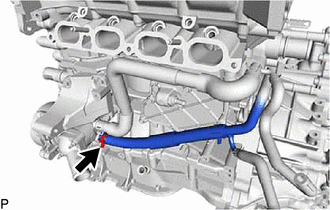
Image 254
15. REMOVE NO. 1 WATER BY-PASS PIPE
a. Remove the 2 bolts and No. 1 water by-pass pipe.
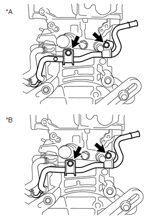
Image 255
*A
for CVT
*B
for Manual Transaxle
16. REMOVE WATER BY-PASS HOSE
a. Slide the clip and remove the water by-pass hose from the cylinder head sub-assembly.
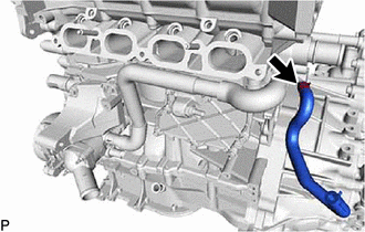
Image 256
17. REMOVE WATER INLET HOSE
a. Slide the 2 clips and remove the water inlet hose.
18. SEPARATE WATER INLET
Refer to PROCEDURE - Step 3
19. REMOVE THERMOSTAT
Refer to PROCEDURE - Step 4
20. REMOVE VACUUM PUMP ASSEMBLY
for TMC Made:
Refer to PROCEDURE - Step 3
for TMMMS Made:
Refer to PROCEDURE - Step 3
21. REMOVE NO. 1 VACUUM PUMP BRACKET
a. Remove the 2 bolts, No. 1 vacuum pump bracket and gasket.
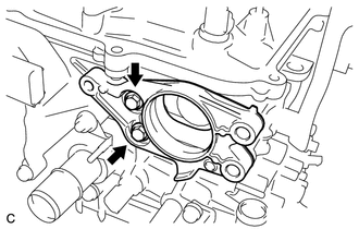
Image 257
22. REMOVE NO. 2 GENERATOR BRACKET
a. Remove the bolt and No. 2 generator bracket from the cylinder head sub-assembly.
23. REMOVE V-RIBBED BELT TENSIONER ASSEMBLY
NOTE:
Do not supply oil to the tensioner when an abnormal noise of the belt occurs.
a. Remove the 2 bolts and V-ribbed belt tensioner assembly from the engine assembly.
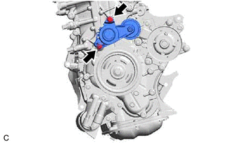
Image 258
24. REMOVE WIRE HARNESS CLAMP BRACKET
a. Remove the bolt and wire harness clamp bracket from the cylinder head cover sub-assembly.
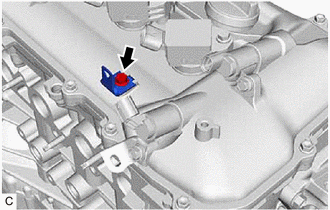
Image 259
25. REMOVE IGNITION COIL ASSEMBLY
Refer to PROCEDURE - Step 1
26. REMOVE ENGINE OIL TEMPERATURE SENSOR