 |
azzdjw00001856
id051400800300
D-code
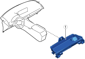
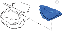
Remove Cover Assembly (Passenger's Side)
1.Remove using the procedure shown in the figure.
azzdjw00001856
|
| Step |
Part name |
|---|---|
|
1
|
Cover assembly
(See
Cover assembly removal note.)
|
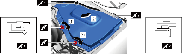
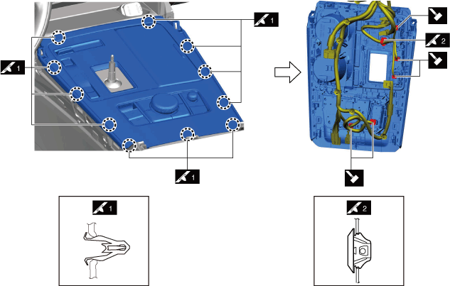
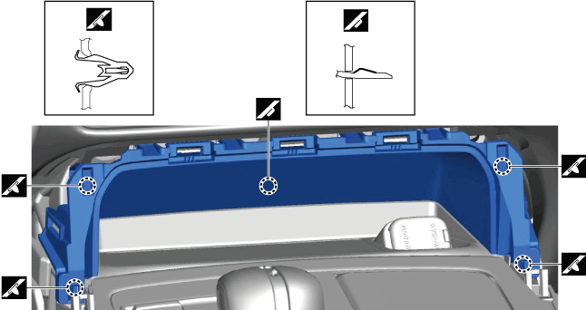
Cover assembly removal note
1.Remove the cover assembly as shown in the figure.
azzdjw00001857
|
| Symbol |
Content |
|---|---|
 |
Servicing procedure
|
Disconnect Negative Lead-Acid Battery Terminal
With e-SKYACTIV PHEV
1.Verify that the charge cable is not connected to the charging port.
2.Keep the driver's door open.
3.Keep the hood open.
4.Keep the main power switched ON (READY on) for 3 s or more.
5.Switch the main power OFF and start measuring the time since the main power was switched OFF using a stopwatch.
6.Switch the main power OFF and wait for 5 min.
7.Disconnect the negative lead-acid battery terminal within 25 min from switching the main power OFF in Step 5 using the following procedure.
azzezw00000929
|
| Symbol |
Content |
|---|---|
 |
5 N·m {51 kgf·cm, 44 in·lbf}
|
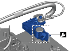
Without e-SKYACTIV PHEV
1.Connect the M-MDS to the DLC-2.
2.Turn ON the engine switch (engine stop).
3.Verify the[BATT_SOC] value using the M-MDS data logger function.
4.Record the [BATT_SOC] value.
5.Turn OFF the engine switch.
6.Disconnect the current sensor connector.
7.Disconnect the negative battery terminal.
azzezw00000929
|
| Symbol |
Content |
|---|---|
| |
5 N·m {51 kgf·cm, 44 in·lbf}
|
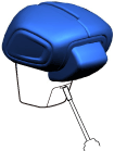
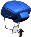
Remove Select Lever Knob
1.Remove using the procedure shown in the figure.
azzezw00000458
|
| Step |
Part name |
|---|---|
|
1
|
Selector lever knob
|
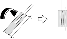
Precautions for removing the select lever and knob
1.To prevent injury, attach protective tape to the tool (width 2 mm {0.08 in} or less, thickness 1 mm {0.04 in} or less ), cutting any excess tape with scissors.
azzdjw00003364
|
| Symbol |
Content |
|---|---|
 |
40 mm {1.6 in}
|
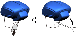
2.Insert the tool as shown in the figure.
azzdjw00003365
|
3.Move the tool in the direction of the arrows as shown in the figure and remove the cover.
azzdjw00003366
|
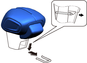
4.Remove the spring while pushing it down.
azzdjw00003367
|
5.Remove the selector level knob.
Selector lever knob installation note
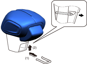
1.Attach the spring to the selector lever knob.
azzdjw00003368
|
2.Attach the cover to the selector lever knob.
azzdjw00003369
|
3.Install the selector lever knob on the selector lever.
Remove Front Console
1.Remove using the procedure shown in the figure.
azzdjw00000622
|
| Step |
Part name |
|---|---|
|
1
|
Front console
(See
Front console removal note.)
|
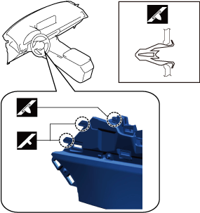
Front console removal note
1.Remove the front console as shown in the figure.
azzezw00000967
|
Remove Shift Panel
1.Remove using the procedure shown in the figure.
azzdjw00000620
|
| Step |
Part name |
|---|---|
|
1
|
Shift panel
(See
Shift panel removal note.)
|
Shift panel removal note
1.Remove the shift panel as shown in the figure.
azzdjw00000621
|
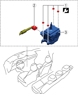
Remove Select Lever
1.Remove using the procedure shown in the figure.
azzezw00000480
|
| Step |
Part name |
 |
|---|---|---|
|
1
|
Nut
|
9.5 N·m {95 kgf·cm, 82 in·lbf}
|
|
2
|
Select lever connector
|
—
|
|
3
|
Selector lever
|
—
|
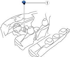
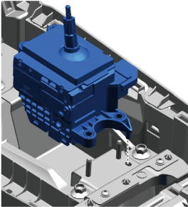
Selector lever knob installation note
1.Insert the pin of the select lever into the positioning hole.
azzdjw00003258
|
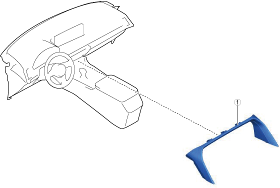
Remove Upper Panel
1.Remove using the procedure shown in the figure.
azzdjw00000618
|
| Step |
Part name |
|---|---|
|
1
|
Upper panel
(See
Upper panel removal note.)
|
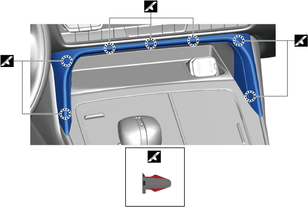
Upper panel removal note
1.Remove the upper panel as shown in the figure
azzdjw00000619
|
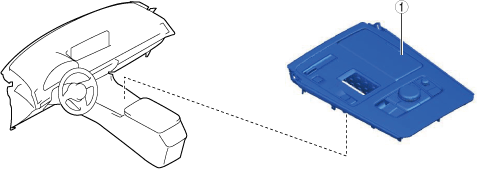
Remove Front Console Box
1.Remove using the procedure shown in the figure.
azzdjw00001608
|
| Step |
Part name |
|---|---|
|
1
|
Front console box
|
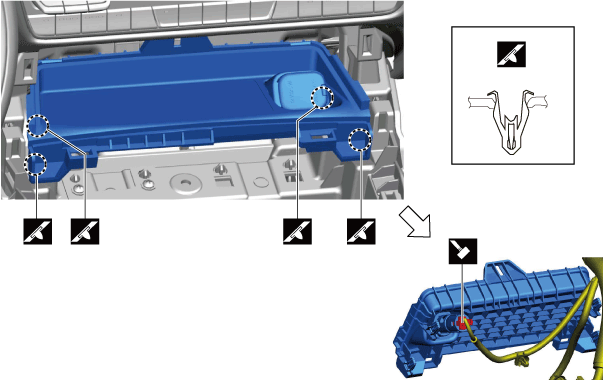
Front console box removal note
1.Remove the front console box as shown in the figure.
azzdjw00001609
|
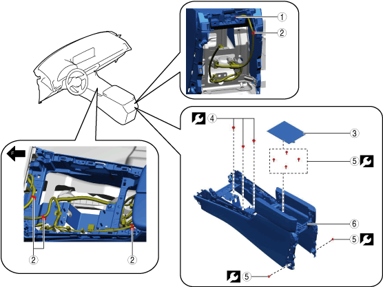
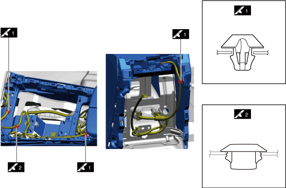
Remove Rear Console
1.Remove using the procedure shown in the figure.
azzdjw00001612
|
| Step |
Part name |
Applicable condition |
|
|---|---|---|---|
|
1
|
Connector
|
With rear console illumination
|
—
|
|
2
|
Wiring harness clip
|
—
|
—
|
|
3
|
Cushion tape
|
—
|
—
|
|
4
|
Bolt
|
—
|
22 N·m {2.25 kgf·m, 16.3 ft·lbf}
|
|
5
|
Bolt
|
—
|
4 N·m {41 kgf·cm, 35 in·lbf}
|
|
6
|
Rear console
(See
Rear console removal note.)
|
—
|
—
|
Wiring harness clip removal note
1.Remove the wiring harness clips as shown in the figure.
azzdjw00001613
|
Rear console removal note
1.Remove the rear console as shown in the figure.
azzdjw00001614
|
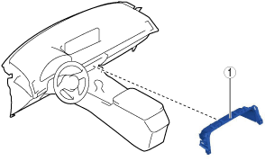
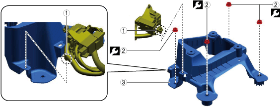
Remove Selector Lever Bracket
1.Remove using the procedure shown in the figure.
azzdjw00003043
|
| Step |
Part name |
|
|---|---|---|
|
1
|
Wiring harness clip
|
—
|
|
2
|
Nut
|
19 N·m {1.95 kgf·m, 14.1 ft·lbf}
|
|
3
|
Selector lever bracket
|
—
|
Install in Reverse Order of Removal
1.Install in the reverse order of removal.
Perform Battery Condition Initial Setting (i-Stop Setting)
Circle: Applicable—: Not applicable
| Purpose |
Operation |
Without M Hybrid Boost (With i-stop) |
|
|---|---|---|---|
| T3 |
PYUL |
||
|
1. Verify that the BATT_SOC value measured when the vehicle is in the shop is
75% or more.
|
1. Using the M-MDS, verify that the PID [BATT_SOC] value is
75% or more.
|
O
|
O
|
|
2. In the following cases, perform a battery inspection. (See
BATTERY INSPECTION.)
• [BATT_SOC] value is less than
75%
• [BATT_SOC] value cannot be verified
|
O
|
O
|
|
|
2. Have the [BATT_SOC] value determined by the PCM.
|
1. Disconnect the negative battery terminal and wait for
5 min or more. (See
NEGATIVE BATTERY TERMINAL DISCONNECTION/CONNECTION.)
|
O
|
O
|
|
3. Have the PCM learn the battery condition.
|
1. Connect the negative battery terminal and wait for
10 s or more. (See
NEGATIVE BATTERY TERMINAL DISCONNECTION/CONNECTION.)
|
O
|
O
|
|
2. Switch the ignition ON (engine off) and wait between
15 s to 60 s.
|
O
|
O
|
|
|
3. Press and hold the i-stop OFF switch for
approx.10 s.
|
O
|
O
|
|
|
4. Verify that the i-stop warning light (amber) illumination changes to the i-stop indicator light (green) flashing.
• If the i-stop warning light (amber) does not turn off, it is possible that the procedure was performed incorrectly, therefore, perform the procedure again from the beginning.
• If the i-stop warning light (amber) flashes, perform a battery inspection. (See
BATTERY INSPECTION.)
|
O
|
O
|
|
|
5. Switch ignition OFF.
|
O
|
O
|
|
|
6. Close the hood.
|
O
|
O
|
|
|
4. Perform idle air control learning.
|
1. Switch the ignition ON (engine on).
|
—
|
O
|
|
2. Turn off the following systems to which electrical load is applied.
• Lighting systems such as headlights.
• Climate control system
• Rear window defogger
|
—
|
O
|
|
|
3. Warm up the engine completely.
|
—
|
O
|
|
|
4. Switch the ignition OFF.
|
—
|
O
|
|
|
5. Verify the i-stop control settings.
|
Perform the following procedure from Step 1 to 5 within
25 s.
|
O
|
O
|
|
1. Switch the ignition ON (engine off) and within
5 s, press and hold the i-stop OFF switch for
3 s or more.
|
O
|
O
|
|
|
2. Verify that the i-stop warning light (amber) is on.
|
O
|
O
|
|
|
3. Switch the ignition ON (engine on).
|
O
|
O
|
|
|
4. Verify that the i-stop warning light (amber) illumination changes to the i-stop indicator light (green) flashing.
• If the i-stop warning light (amber) illuminates or flashes, perform a battery inspection. (See
BATTERY INSPECTION.)
|
O
|
O
|
|
|
5. Press and hold the i-stop OFF switch for
approx. 3 s.
|
O
|
O
|
|
|
6. Wait for
30 s while idling (with no electrical load).
|
O
|
O
|
|
|
7. Perform engine racing for a minimum
10 times and a maximum
20 times. Then, wait for
30 s while idling (with no electrical load).
• After the flashing i-stop indicator light (green) turns off, switch the ignition OFF.
• If the i-stop indicator light (green) does not turn off, it is possible that there is a problem with the M Hybrid system, therefore, perform an inspection of the M Hybrid system.
|
—
|
—
|
|
|
8. Maintain the idling condition (with no electrical load) until the i-stop indicator light (green) flashing turns off.
|
O
|
O
|
|
|
9. After the flashing i-stop indicator light (green) turns off, switch the ignition OFF.
|
O
|
O
|
|
|
6. Perform an i-stop control operation verification.
|
1. Switch the ignition ON (engine on).
|
O
|
O
|
|
2. Accelerate to a vehicle speed of
15 km/h in
approx. 5 s without operating the steering wheel.
|
O
|
O
|
|
|
3. Stop the vehicle.
|
O
|
O
|
|
|
4. Verify that the engine stops and restarts by the i-stop control.
|
O
|
O
|
|
|
5. Switch the ignition OFF.
|
O
|
O
|
|
Complete Configuration (If Parts Are Replaced)
Complete Global Central Configuration (GCC)
1.Switch the main power OFF.
2.Switch the main power ON (READY off).
Perform Power Liftgate Initialization
1.Close the power liftgate manually.
Initialize Power Outer Mirror Retract/Return Function
Power outer mirrors are in returned position
1.Switch the ignition ON (engine off)/switch the main power ON (READY off).
2.Press the power outer mirror retract/return switch to retract the power outer mirrors.
3.Press the power outer mirror retract/return switch again to return the power outer mirrors.
4.Switch the ignition OFF/switch the main power OFF.
Power outer mirrors are in retracted position
1.Switch the ignition ON (engine off)/switch the main power ON (READY off).
2.Press the power outer mirror retract/return switch 2 times to return the power outer mirrors.
3.Switch the ignition OFF/switch the main power OFF.