|
azzdjw00000055
id01170095392a
D-code
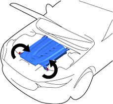
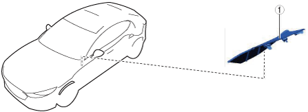
Remove Capsule Cover
1.Remove using the procedure shown in the figure.
azzdjw00000055
|
| Procedure |
Part name |
Applicable condition |
|---|---|---|
|
1
|
Capsule cover
|
Continuous
|
Capsule cover removal note
1.Turn the fasteners as shown in the figure.
azzdjw00000054
|
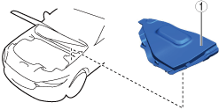
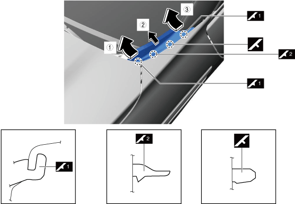
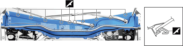
Remove Passenger’s Side Cowl Grille Cover
1.Remove using the procedure shown in the figure.
azzdjw00001856
|
| Procedure |
Part name |
Applicable condition |
|---|---|---|
|
1
|
Cowl grille cover
|
Continuous
|
Cowl grille cover removal note
1.Remove the cowl grille cover as shown in the figure.
azzdjw00003822
|
| Symbol |
Content |
|---|---|
 |
Servicing procedure
|
Disconnect Negative Lead-Acid Battery Terminal
With e-SKYACTIV PHEV
1.Verify that the charge cable is not connected to the charging port.
2.Keep the driver's door open.
3.Keep the main power switched ON (READY on) for 3 s or more.
4.Switch the main power OFF and start measuring the time since the main power was switched OFF using a stopwatch.
5.Switch the main power OFF and wait for 5 min.
6.Disconnect the negative lead-acid battery terminal within 25 min from switching the main power OFF in Step 5 using the following procedure.
azzdjw00002329
|
Without e-SKYACTIV PHEV
1.Connect the M-MDS to the DLC-2.
2.Turn ON the engine switch (engine stop).
3.Verify the[BATTlowbarSOC] value using the M-MDS data logger function.
4.Record the [BATT_SOC] value.
5.Turn OFF the engine switch.
6.Disconnect the current sensor connector.
7.Disconnect the negative battery terminal.
azzdjw00002329
|
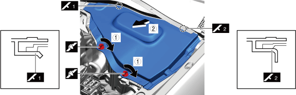
Remove Passenger's Side Front Fender Molding
1.Remove using the procedure shown in the figure.
azzdjw00003814
|
| Procedure |
Part name |
Applicable condition |
|---|---|---|
|
1
|
Front fender molding
|
Continuous
|
Front fender molding removal note
1.Remove the front fender molding as shown in the figure.
azzdjw00003813
|
| Symbol |
Content |
|---|---|
| |
Servicing procedure
|
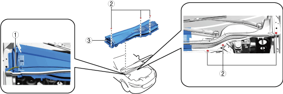
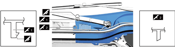
Remove Cowl Grille (Right Side)
1.Remove using the procedure shown in the figure.
azzdjw00001868
|
| Procedure |
Part name |
Applicable condition |
|---|---|---|
|
1
|
Washer hose
|
Continuous
|
|
2
|
Fastener
|
Continuous
|
|
3
|
Cowl grille (right side)
|
Continuous
|
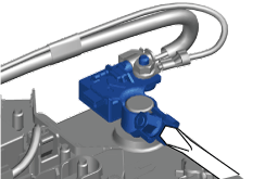
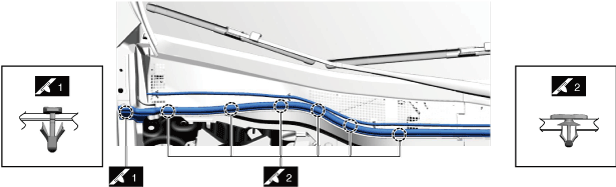
Cowl grille (right side) removal note
1.Partially peel back the cowl grille weatherstrip and washer hose until the cowl grille (right side) can be removed as shown in the figure.
azzdjw00002289
|
2.Release the cowl grille latch.
azzdjw00002290
|
3.Move the cowl grille (left side) to release the pins and hooks.
azzdjw00002291
|
4.Remove the cowl grille (right side).
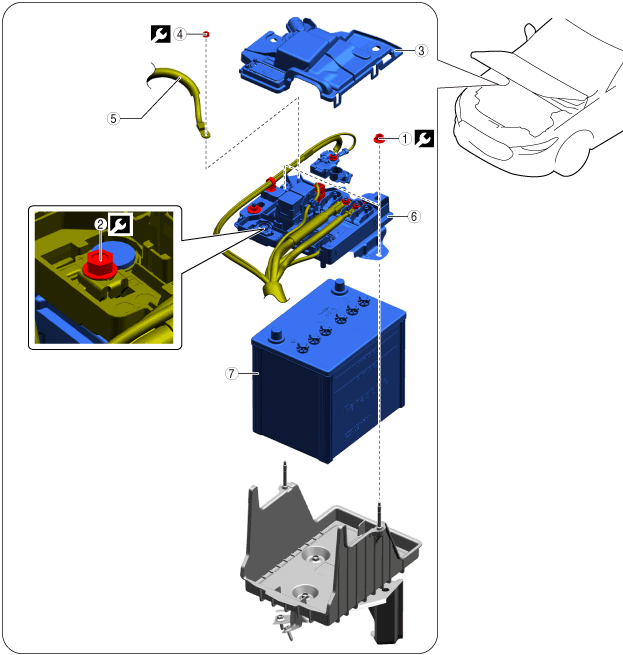
Remove Lead-Acid Battery
1.Remove using the procedure shown in the figure.
azzezw00000668
|
| Procedure |
Part name |
Applicable condition |
 |
|---|---|---|---|
|
1
|
Nut
|
Continuous
|
6 N·m {61 kgf·cm, 53 in·lbf}
|
|
2
|
Bolt
|
Continuous
|
5 N·m {51 kgf·cm, 44 in·lbf}
|
|
3
|
Lead-acid battery cap
|
Continuous
|
—
|
|
4
|
Nut
|
Continuous
|
9.5 N·m {95 kgf·cm, 82 in·lbf}
|
|
5
|
Starter wiring harness
|
Continuous
|
—
|
|
6
|
Lead-acid battery (plus) terminal component
|
Continuous
|
—
|
|
7
|
Lead-acid battery
|
Continuous
|
—
|
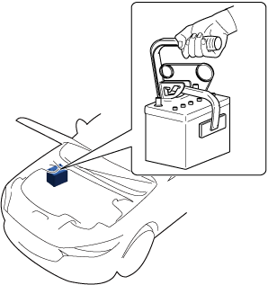
Lead-acid battery removal note
1.Remove the battery using a commercially available battery catcher as shown in the figure.
azzezw00000669
|
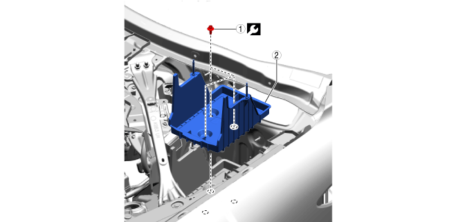
Remove the battery tray
1.Remove using the procedure shown in the figure.
ac6wzw00000663
|
| Procedure |
Part name |
Applicable condition |
|
|---|---|---|---|
|
1
|
Bolt
|
Continuous
|
26 N·m {2.65 kgf·m, 19.2 ft·lbf}
|
|
2
|
Battery Tray
|
Continuous
|
—
|
Operation After Replacing Battery
1.Close all doors.
2.Switch the ignition ON.
3.When a warning message or the like is displayed on the display, proceed to the next step after erasing the screen by operating the INFO switch.
4.the selector lever to the P position.
5.Perform the following work with the brake pedal depressed.
6.Switch the ignition OFF.
Perform Battery Condition Initial Setting (i-Stop Setting)
Circle: Applicable—: Not applicable
| Purpose |
Operation |
With M Hybrid |
Without M Hybrid |
|
|---|---|---|---|---|
| T3 |
PYUL |
|||
|
1. Verify that the BATT_SOC value measured when the vehicle is in the shop is 75% or more.
|
1. Using the M-MDS, verify that the PID [BATT_SOC] value is 75% or more.
|
O
|
O
|
O
|
|
2. In the following cases, perform a battery inspection. (See
BATTERY INSPECTION.)
• [BATT_SOC] value is less than 75%
• [BATT_SOC] value cannot be verified
|
O
|
O
|
O
|
|
|
2. Have the [BATT_SOC] value determined by the PCM.
|
1. Disconnect the negative battery terminal and wait for 5 min or more. (See
NEGATIVE BATTERY TERMINAL DISCONNECTION/CONNECTION.)
|
O
|
O
|
O
|
|
2. Disconnect the current sensor connector.
|
O
|
O
|
O
|
|
|
3. Have the PCM learn the battery condition.
|
1. Connect the negative battery terminal and wait for 10 s or more. (See
NEGATIVE BATTERY TERMINAL DISCONNECTION/CONNECTION.)
|
O
|
O
|
O
|
|
2. Connect the current sensor connector.
|
O
|
O
|
O
|
|
|
3. Switch the ignition ON (engine off) and wait between 15 s to 60 s.
|
—
|
O
|
O
|
|
|
4. Press and hold the i-stop OFF switch for approx.10 s.
|
—
|
O
|
O
|
|
|
5. Verify that the i-stop warning light (amber) illumination changes to the i-stop indicator light (green) flashing.
• If the i-stop warning light (amber) does not turn off, it is possible that the procedure was performed incorrectly, therefore, perform the procedure again from the beginning.
• If the i-stop warning light (amber) flashes, perform a battery inspection. (See
BATTERY INSPECTION.)
|
—
|
O
|
O
|
|
|
6. Switch ignition OFF.
|
—
|
O
|
O
|
|
|
7. Close the hood.
|
O
|
O
|
O
|
|
|
4. Perform idle air control learning.
|
1. Switch the ignition ON (engine on).
|
—
|
—
|
O
|
|
2. Turn off the following systems to which electrical load is applied.
• Lighting systems such as headlights.
• Climate control system
• Rear window defogger
|
—
|
—
|
O
|
|
|
3. Warm up the engine completely.
|
—
|
—
|
O
|
|
|
4. Switch the ignition OFF.
|
—
|
—
|
O
|
|
|
5. Verify the i-stop control settings.
|
Perform the following procedure from Step 1 to 5 within 25 s.
|
—
|
O
|
O
|
|
1. Switch the ignition ON (engine off) and within 5 s, press and hold the i-stop OFF switch for 3 s or more.
|
—
|
O
|
O
|
|
|
2. Verify that the i-stop warning light (amber) is on.
|
—
|
O
|
O
|
|
|
3. Switch the ignition ON (engine on).
|
—
|
O
|
O
|
|
|
4. Verify that the i-stop warning light (amber) illumination changes to the i-stop indicator light (green) flashing.
• If the i-stop warning light (amber) illuminates or flashes, perform a battery inspection. (See
BATTERY INSPECTION.)
|
—
|
O
|
O
|
|
|
5. Press and hold the i-stop OFF switch for approx. 3 s.
|
—
|
O
|
O
|
|
|
6. Wait for 30 s while idling (with no electrical load).
|
—
|
O
|
O
|
|
|
7. Perform engine racing for a minimum 10 times and a maximum 20 times. Then, wait for 30 s while idling (with no electrical load).
• After the flashing i-stop indicator light (green) turns off, switch the ignition OFF.
• If the i-stop indicator light (green) does not turn off, it is possible that there is a problem with the M Hybrid system, therefore, perform an inspection of the M Hybrid system.
|
—
|
—
|
—
|
|
|
8. Maintain the idling condition (with no electrical load) until the i-stop indicator light (green) flashing turns off.
|
—
|
O
|
O
|
|
|
9. After the flashing i-stop indicator light (green) turns off, switch the ignition OFF.
|
—
|
O
|
O
|
|
|
6. Perform an i-stop control operation verification.
|
1. Switch the ignition ON (engine on).
|
—
|
O
|
O
|
|
2. Accelerate to a vehicle speed of 15 km/h in approx. 5 s without operating the steering wheel.
|
—
|
O
|
O
|
|
|
3. Stop the vehicle.
|
—
|
O
|
O
|
|
|
4. Verify that the engine stops and restarts by the i-stop control.
|
—
|
O
|
O
|
|
|
5. Switch the ignition OFF.
|
—
|
O
|
O
|
|