 |
id01101a800800
D-code
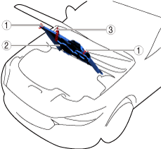
Open Capsule Cover
1.Open in the order indicated in the table.
ac6wzw00000012
|
| Step |
Part name |
|---|---|
|
1
|
Rotating fastener
|
|
2
|
Capsule cover
|
|
3
|
Clip
|
Opening capsule cover note
1.Open the capsule cover as shown in the figure.
ac6wzw00000013
|
| Symbol |
Content |
|---|---|
 |
Servicing procedure
|
Closing capsule cover note
1.Close the capsule cover as shown in the figure.
ac6wzw00000014
|
| Symbol |
Content |
|---|---|
 |
Servicing procedure
|
Remove Front Under Cover No.2
1.Remove using the procedure shown in the figure.
azzdjw00000583
|
| Step |
Part name |
 |
|---|---|---|
|
1
|
Bolt
|
11 N·m {110 kgf·cm, 95 in·lbf}
|
|
2
|
Fastener
|
—
|
|
3
|
Front under cover No.2
|
—
|
Remove Water Pump Drive Belt
1.Remove in the order indicated in the table.
azzdjw00004394
|
| Step |
Part name |
|---|---|
|
1
|
Water Pump Drive Belt
|
Water pump drive belt removal note
1.Apply a cloth to the water pump drive belt as shown in the figure.
azzdjw00004395
|
|
1
|
Rag
|
|
2
|
Water Pump Drive Belt
|
2.Pull the cloth in the direction of the arrow and rotate the crankshaft pulley clockwise.
azzdjw00004396
|
|
1
|
Rag
|
|
2
|
Crankshaft pulley
|
3.Remove the water pump drive belt.
Water pump drive belt installation note
1.Set one side of the water pump drive belt in the groove of the crankshaft pulley.
2.Set the other side of the water pump drive belt in the step of the water pump pulley.
azzdjw00004397
|
|
1
|
Water Pump Drive Belt
|
|
2
|
Water pump pulley
|
3.Pushing up the belt so that it is fitted in from the step of the water pump pulley to the groove of the pulley, rotate the crankshaft pulley clockwise.
azzdjw00004398
|
|
1
|
Water Pump Drive Belt
|
|
2
|
Water pump pulley
|
4.After the belt is installed, rotate the crankshaft pulley clockwise approx. 180° and verify that the water pump drive belt is installed correctly.
Remove Crankshaft Pulley
1.Remove using the procedure shown in the figure.
azzdjw00006268
|
| Procedure |
Part name |
 |
 |
|---|---|---|---|
|
1
|
Crankshaft pulley lock bolt
|
49 B011 105
205-072 (component part or 49 UN20 5072)
|
110 N·m {11.2 kgf·m, 81.15 ft·lbf}
+55—65°
|
|
2
|
Crankshaft pulley
|
—
|
—
|
Crankshaft Pulley Lock Bolt Removal Note
1.Install the SST to the crankshaft pulley to lock the crankshaft against rotation.
azzdjw00006271
|
| Symbol |
Content |
|---|---|
 |
49 B011 105
|
 |
205-072 (component part for 49 UN20 5072)
|
2.Remove the crankshaft pulley lock bolt.
Crankshaft pulley lock bolt installation note
1.Install the SST to the crankshaft pulley to lock the crankshaft against rotation.
azzdjw00006273
|
| Symbol |
Content |
|---|---|
 |
49 B011 105
|
 |
205-072 (component part for 49 UN20 5072)
|
2.Tighten the crankshaft pulley lock bolt in two steps.
Replace Front Oil Seal
1.Remove using the procedure shown in the figure.
azzdjw00005480
|
| Procedure |
Part name |
 |
 |
 |
|---|---|---|---|---|
|
1
|
Crankshaft pulley lock bolt
|
49 G028 205
|
Replacement part
|
Engine oil
|
Front Oil Seal Removal Note
1.Remove the front oil seal lip using a utility knife.
2.Remove the front oil seal using a flathead screwdriver with the tip protected by a cloth to prevent damage to the crankshaft.
azzdjw00005484
|
Front Oil Seal Installation Note
1.Apply engine oil to the inner surface of the bew front oil seal.
2.Insert the front oil seal into the engine front cover by hand.
3.Tap the front oil seal in using the SST.
azzdjw00005485
|
| Symbol |
Content |
|---|---|
 |
0—1 mm {0.00—0.03 in}
|
 |
49 G028 205
|
Install in Reverse Order of Removal
1.Install in the reverse order of removal.