

FUEL PUMP UNIT [SKYACTIV-G]
SECTION 1: FUEL PUMP UNIT REMOVAL/INSTALLATION
Warning
- Highly pressurized fuel may spray out if the fuel line is cut. Due to the following dangers occurring with a fuel spray, always complete the “Fuel Line Safety Procedure” to prevent the fuel from spraying.
― Fuel may cause irritation if it comes in contact with skin and eyes.
― If fuel ignites and causes a fire, it may lead to serious injury or death, and damage to property and facilities. - A person charged with static electricity could cause a fire or explosion, resulting in death or serious injury. Before performing work on the fuel system, discharge static electricity by touching the vehicle body.
Caution
• Disconnecting/connecting the quick release connector without cleaning it may cause damage to the fuel pipe and quick release connector. Always clean the quick release connector joint area before disconnecting/connecting using a cloth or soft brush, and make sure that it is free of foreign material.

- Complete the “BEFORE SERVICE PRECAUTION”.
Warning
- If the fuel gauge level indicates 8/16 or more, refer to the [FUEL DRAINING PROCEDURE] and drain the fuel.
- Disconnect the negative battery terminal.
- Remove the rear seat cushion.


| 1 | Fuel pump unit connector |
| 2 | Quick release connector |
| 3 | Set plate component |
| 4 | Fuel pump unit |
| 5 | Packing |

- Install in the reverse order of removal.
- Complete the “AFTER SERVICE PRECAUTION”.

Set Plate Component Installation Note
- Align the reinforcement part of the set plate component near the pipe area of the fuel pump unit as shown in the figure and assemble.
SECTION 2: FUEL PUMP UNIT DISASSEMBLY/ASSEMBLY

- Complete the “BEFORE SERVICE PRECAUTION”.
Caution
- Because the fuel surface is higher than the fuel pump unit installation surface, if the set plate is removed, it may result in fuel leakage. If the fuel gauge level indicates 3/4 or more, refer to the fuel draining procedure and drain 20 liters of fuel.
- Remove the fuel pump unit.
- Disassemble in the order indicated in the table.
- Assemble in the reverse order of disassembly.
- Install in the reverse order of removal.
- Complete the “AFTER SERVICE PRECAUTION”.
2WD
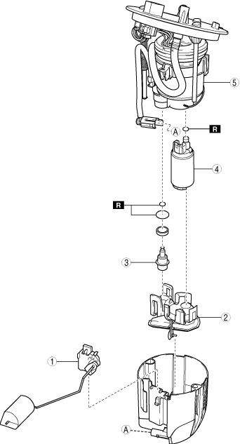
| 1 | Fuel gauge sender unit |
| 2 | Fuel filter (low-pressure) |
| 3 | Pressure regulator |
| 4 | Fuel pump |
| 5 | Fuel filter (high-pressure) |
AWD
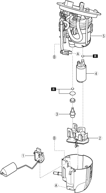
| 1 | Fuel gauge sender unit |
| 2 | Fuel filter (low-pressure) |
| 3 | Pressure regulator |
| 4 | Fuel pump |
| 5 | Fuel filter (high-pressure) |
SECTION 3: FUEL PUMP UNIT INSPECTION
Fuel Pump Operation Inspection
- Connect the M-MDS to the DLC-2.
- Perform the KOEO self-test.
- If a DTC is detected, repair the malfunctioning location according to the applicable DTC troubleshooting.
- Remove the fuel-filler cap.
- Switch the ignition ON (engine off).
- Verify the following operation sounds for approx. 1 s after the ignition is switched ON (engine off).
- Fuel pump relay (OFF → ON → OFF)
- Fuel pump (Verify direct operation sound from fuel-filler opening)
― If the operation sounds cannot be verified, inspect the following and repair or replace the malfunctioning location.
Fuel pump relay operation sound cannot be verified - Fuel pump relay (stuck open/closed)
- Wiring harness between IG1 relay and fuel pump relay terminal E (short, open circuit)
- Wiring harness between fuel pump relay terminal A and PCM terminal 2AW (short, open circuit)
Fuel pump operation sound cannot be verified - Fuel pump relay (stuck open or open circuit in internal circuit)
- Wiring harness between battery and fuel pump relay terminal D
- Wiring harness between fuel pump relay terminal C and fuel pump control module terminal 2B (short, open circuit)
- Fuel pump unit (inspect for continuity)
- Wiring harness between fuel pump unit terminal A and fuel pump control module terminal 2C (short, open circuit)
- Wiring harness between fuel pump unit terminal D and fuel pump control module terminal 2E (short, open circuit)
- Wiring harness between fuel pump unit terminal B and fuel pump control module terminal 2A (short, open circuit)
- Wiring harness between fuel pump unit terminal E and fuel pump control module terminal 2F (short, open circuit)
- Wiring harness between fuel pump control module terminal 2D and body ground (open circuit, ground point looseness or lifting)
― If the inspection items are normal, inspect the fuel pump control module.
Continuity Inspection
- Disconnect the negative battery terminal.
- Disconnect the fuel pump unit connector.
