

FUEL TANK REMOVAL/INSTALLATION AND INSPECTION [SKYACTIV-G]
FUEL TANK REMOVAL/INSTALLATION [SKYACTIV-G]
Warning
- Highly pressurized fuel may spray out if the fuel line is cut. Due to the following dangers occurring with a fuel spray, always complete the “Fuel Line Safety Procedure” to prevent the fuel from spraying.
― Fuel may cause irritation if it comes in contact with skin and eyes.
― If fuel ignites and causes a fire, it may lead to serious injury or death, and damage to property and facilities. - A person charged with static electricity could cause a fire or explosion, resulting in death or serious injury. Before performing work on the fuel system, discharge static electricity by touching the vehicle body.
Caution - Disconnecting/connecting the quick release connector without cleaning it may cause damage to the fuel pipe and quick release connector. Always clean the quick release connector joint area before disconnecting/connecting using a cloth or soft brush, and make sure that it is free of foreign material.
- Level the vehicle.
- Complete the “BEFORE SERVICE PRECAUTION”. (See BEFORE SERVICE PRECAUTION [SKYACTIV-G (WITH CYLINDER DEACTIVATION (E))].)
- Drain the fuel. (See FUEL DRAINING PROCEDURE [SKYACTIV-G (WITH CYLINDER DEACTIVATION (E))].)
- Remove the rear seat cushion. (See REAR SEAT CUSHION REMOVAL/INSTALLATION.)
- Remove the service hole cover.
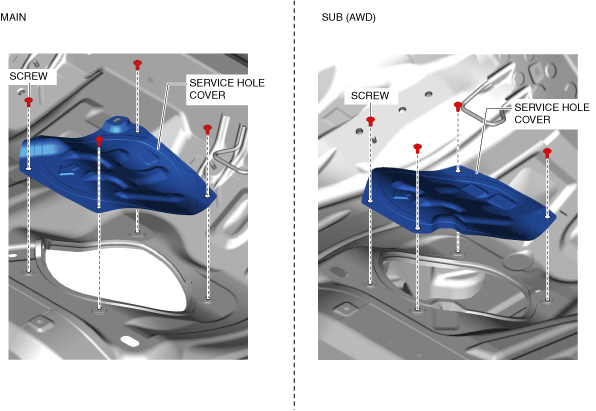
- Disconnect the following parts:
- Fuel pump unit connector
- Fuel gauge sender unit (AWD)
- Quick release connector (See QUICK RELEASE CONNECTOR (FUEL SYSTEM) REMOVAL/INSTALLATION [SKYACTIV-G (WITH CYLINDER DEACTIVATION (E))].)
- Remove the floor under cover No.1 (LH). (See FLOOR UNDER COVER REMOVAL/INSTALLATION.)
- Remove the floor under cover No.2. (See FLOOR UNDER COVER REMOVAL/INSTALLATION.)
- Remove the TWC and HO2S as a single unit. (See EXHAUST SYSTEM REMOVAL/INSTALLATION [SKYACTIV-G (WITH CYLINDER DEACTIVATION (E))].)
- Remove the propeller shaft. (AWD) (See PROPELLER SHAFT REMOVAL/INSTALLATION [(E)].)
- Remove the insulator (middle). (See EXHAUST SYSTEM REMOVAL/INSTALLATION [SKYACTIV-G (WITH CYLINDER DEACTIVATION (E))].)
- Remove in the order indicated in the table.
- Install in the reverse order of removal.
- Complete the “AFTER SERVICE PRECAUTION”. (See AFTER SERVICE PRECAUTION [SKYACTIV-G (WITH CYLINDER DEACTIVATION (E))].)
2WD
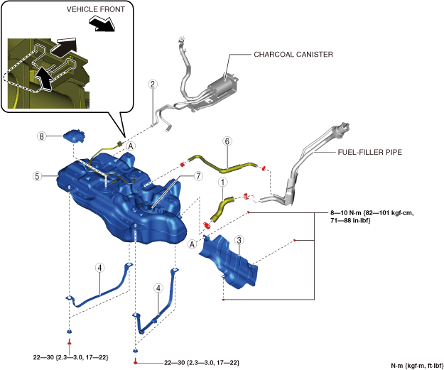
| 1 | Joint hose(See Joint Hose Installation Note.) |
| 2 | Evaporative hose(See Evaporative Hose Installation Note.) |
| 3 | Fuel tank insulator |
| 4 | Fuel tank strap |
| 5 | Fuel tank(See Fuel Tank Removal Note.) |
| 6 | Breather hose(See Breather Hose Installation Note (2WD).) |
| 7 | Fuel pump unit(See FUEL PUMP UNIT REMOVAL/INSTALLATION [SKYACTIV-G (WITH CYLINDER DEACTIVATION (E))].) |
| 8 | Cover |
AWD
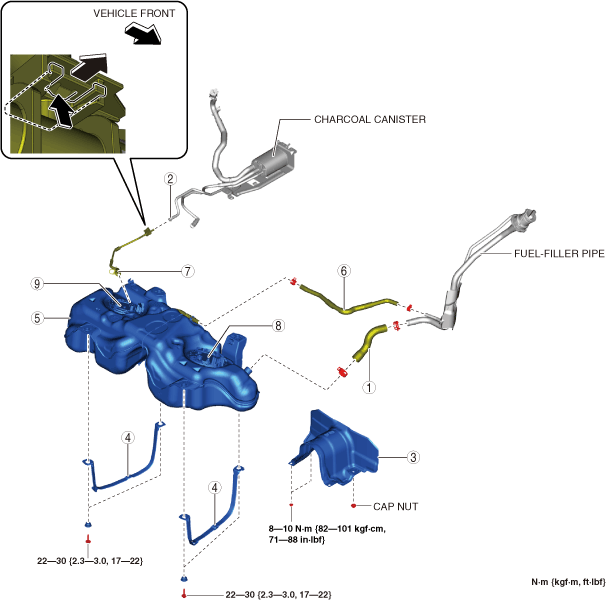
| 1 | Joint hose(See Joint Hose Installation Note.) |
| 2 | Evaporative hose(See Evaporative Hose Installation Note.) |
| 3 | Fuel tank insulator |
| 4 | Fuel tank strap |
| 5 | Fuel tank(See Fuel Tank Removal Note.) |
| 6 | Breather hose |
| 7 | Quick release connector(See QUICK RELEASE CONNECTOR (FUEL SYSTEM) REMOVAL/INSTALLATION [SKYACTIV-G (WITH CYLINDER DEACTIVATION (E))].) |
| 8 | Fuel pump unit(See FUEL PUMP UNIT REMOVAL/INSTALLATION [SKYACTIV-G (WITH CYLINDER DEACTIVATION (E))].) |
| 9 | Fuel gauge sender unit(See FUEL GAUGE SENDER UNIT REMOVAL/INSTALLATION [(E)].) |
Fuel Tank Removal Note
- Disconnect the breather hose from the fuel-filler pipe side.
- Remove the following parts as single unit:
- Breather hose
- Fuel pump unit
- Fuel tank
- Cover (2WD)
- Quick release connector (AWD)
- Fuel gauge sender unit (AWD)
- Remove the fuel tank.
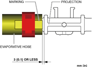
Evaporative Hose Installation Note
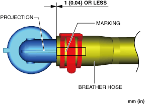
1. Align the evaporative hose marking with the projection on the pipe as shown in the figure and assemble.
 |
Breather Hose Installation Note (2WD)
- Align the breather hose marking with the projection on the pipe as shown in the figure and assemble.
Fuel tank side
 |
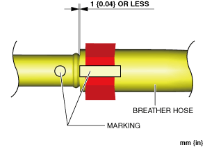
2. Align the breather hose marking with the fuel-filler pipe marking as shown in the figure and assemble.
Fuel-filler pipe side
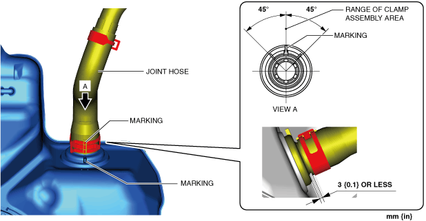
Joint Hose Installation Note
- Align the joint hose marking with the pipe marking as shown in the figure and assemble.
Fuel tank side
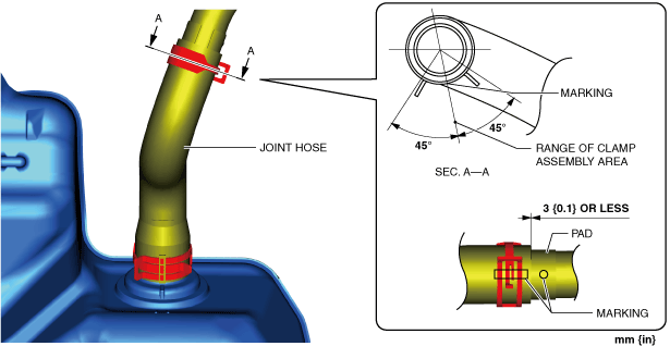
- Align the joint hose marking with the fuel-filler pipe marking as shown in the figure and assemble.
Fuel-filler pipe side
FUEL TANK INSPECTION [SKYACTIV-G]
Warning
- Highly pressurized fuel may spray out if the fuel line is cut. Due to the following dangers occurring with a fuel spray, always complete the “Fuel Line Safety Procedure” to prevent the fuel from spraying.
― Fuel may cause irritation if it comes in contact with skin and eyes.
― If fuel ignites and causes a fire, it may lead to serious injury or death, and damage to property and facilities. - A person charged with static electricity could cause a fire or explosion, resulting in death or serious injury. Before performing work on the fuel system, discharge static electricity by touching the vehicle body.
Note - The rollover valve and the fuel shut-off valve (built into the fuel tank) and also fuel tank leakage are inspected in this inspection.
2WD
- Level the vehicle.
- Complete the “BEFORE SERVICE PRECAUTION”. (See BEFORE SERVICE PRECAUTION [SKYACTIV-G (WITH CYLINDER DEACTIVATION (E))].)
- Drain the fuel. (See FUEL DRAINING PROCEDURE [SKYACTIV-G (WITH CYLINDER DEACTIVATION (E))].)
- Remove the fuel tank and fuel pump unit as a single unit. (See FUEL TANK REMOVAL/INSTALLATION [SKYACTIV-G (WITH CYLINDER DEACTIVATION (E))])
- Perform the following procedure to verify fuel tank airtightness.
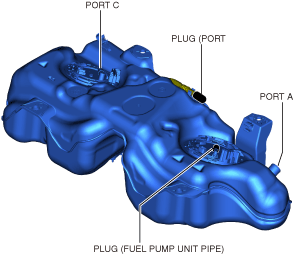
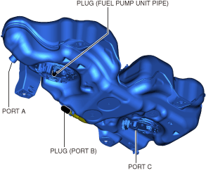
(1) Plug the fuel pump unit pipe, and ports B and C.
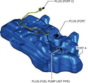
(2) Apply pressure of 5.9 kPa {44 mmHg, 1.7 inHg} to port A and wait for a while.
(3) Verify that there is no change in the pressure and no air leakage from the fuel tank.
- If there is air leakage, replace the fuel tank. (See FUEL TANK REMOVAL/INSTALLATION [SKYACTIV-G (WITH CYLINDER DEACTIVATION (E))].)
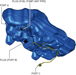
6. Remove the port C plug
- Place the fuel tank in a level position.
- Close port A and apply 5.9 kPa {44 mmHg, 1.7 inHg} of pressure to port C, and leave it in this condition momentarily.
- Open port A and verify that the pressure decreases from 5.9 kPa {44 mmHg, 1.7 inHg}.
- If it cannot be verified, replace the fuel tank. (See FUEL TANK REMOVAL/INSTALLATION [SKYACTIV-G (WITH CYLINDER DEACTIVATION (E))].)
- Close port A and apply -2.0 kPa {-15 mmHg, -0.59 inHg} vacuum to port C, and leave it in this condition momentarily.
- Open port A and verify that the -2.0 kPa {-15 mmHg, -0.59 inHg} negative pressure condition restores to near positive pressure.
- If it cannot be verified, replace the fuel tank. (See FUEL TANK REMOVAL/INSTALLATION [SKYACTIV-G (WITH CYLINDER DEACTIVATION (E))].)
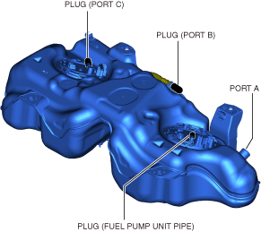
- Turn the fuel tank upside down.
- Apply pressure of 5.9 kPa {44 mmHg, 1.7 inHg} to port A and wait for a while.
- Verify that there is no change in the pressure and no air leakage from the port C.
- If there is air leakage, replace the fuel tank. (See FUEL TANK REMOVAL/INSTALLATION [SKYACTIV-G (WITH CYLINDER DEACTIVATION (E))].)
AWD
- Level the vehicle.
- Complete the “BEFORE SERVICE PRECAUTION”. (See BEFORE SERVICE PRECAUTION [SKYACTIV-G (WITH CYLINDER DEACTIVATION (E))].)
- Drain the fuel. (See FUEL DRAINING PROCEDURE [SKYACTIV-G (WITH CYLINDER DEACTIVATION (E))].)
- Remove the fuel tank and fuel pump unit and fuel gauge sender unit as a single unit. (See FUEL TANK REMOVAL/INSTALLATION [SKYACTIV-G (WITH CYLINDER DEACTIVATION (E))])
- Perform the following procedure to verify fuel tank airtightness.
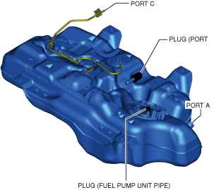
(1) Plug the fuel pump unit pipe, and ports B and C.
(2) Apply pressure of 5.9 kPa {44 mmHg, 1.7 inHg} to port A and wait for a while.
(3) Verify that there is no change in the pressure and no air leakage from the fuel tank.
- If there is air leakage, replace the fuel tank. (See FUEL TANK REMOVAL/INSTALLATION [SKYACTIV-G (WITH CYLINDER DEACTIVATION (E))].)
6. Remove the port C plug
- Place the fuel tank in a level position.
- Close port A and apply 5.9 kPa {44 mmHg, 1.7 inHg} of pressure to port C, and leave it in this condition momentarily.
- Open port A and verify that the pressure decreases from 5.9 kPa {44 mmHg, 1.7 inHg}.
- If it cannot be verified, replace the fuel tank. (See FUEL TANK REMOVAL/INSTALLATION [SKYACTIV-G (WITH CYLINDER DEACTIVATION (E))].)
- Close port A and apply -2.0 kPa {-15 mmHg, -0.59 inHg} vacuum to port C, and leave it in this condition momentarily.
- Open port A and verify that the -2.0 kPa {-15 mmHg, -0.59 inHg} negative pressure condition restores to near positive pressure.
- If it cannot be verified, replace the fuel tank. (See FUEL TANK REMOVAL/INSTALLATION [SKYACTIV-G (WITH CYLINDER DEACTIVATION (E))].)
- Turn the fuel tank upside down.
- Apply pressure of 5.9 kPa {44 mmHg, 1.7 inHg} to port A and wait for a while.
- Verify that there is no change in the pressure and no air leakage from the port C.
- If there is air leakage, replace the fuel tank. (See FUEL TANK REMOVAL/INSTALLATION [SKYACTIV-G (WITH CYLINDER DEACTIVATION (E))].)